Stowage bin with shear fittings

a technology of shear fittings and bins, which is applied in the field of storage bins, can solve the problems of affecting the quality of the product, the cost of manufacturing and assembly and the bulky and heavy nature of conventional overhead storage bins

Active Publication Date: 2011-11-01
THE BOEING CO
View PDF31 Cites 9 Cited by
  • Summary
  • Abstract
  • Description
  • Claims
  • Application Information

AI Technical Summary

Problems solved by technology

On the other hand, these conventional designs also present a number of drawbacks.
For example, conventional overhead stowage bins are often bulky and somewhat heavy.
In addition, conventional overhead stowage bins can be rather costly to manufacture and assemble.
These drawbacks are becoming increasingly significant, as aircraft designers strive to develop more and more efficient aircraft designs.

Method used


Image

  • Stowage bin with shear fittings
  • Stowage bin with shear fittings
  • Stowage bin with shear fittings

Examples


Embodiment Construction

[0031]In the following detailed description, reference is made to the accompanying drawings that form a part hereof, and in which is shown by way of illustration specific illustrative embodiments in which the invention may be practiced. These embodiments are described in sufficient detail to enable those skilled in the art to practice the invention, and it is to be understood that other embodiments may be utilized and that logical, mechanical, and electrical changes may be made without departing from the spirit and scope of the present invention. The following detailed description is, therefore, not to be taken in a limiting sense.

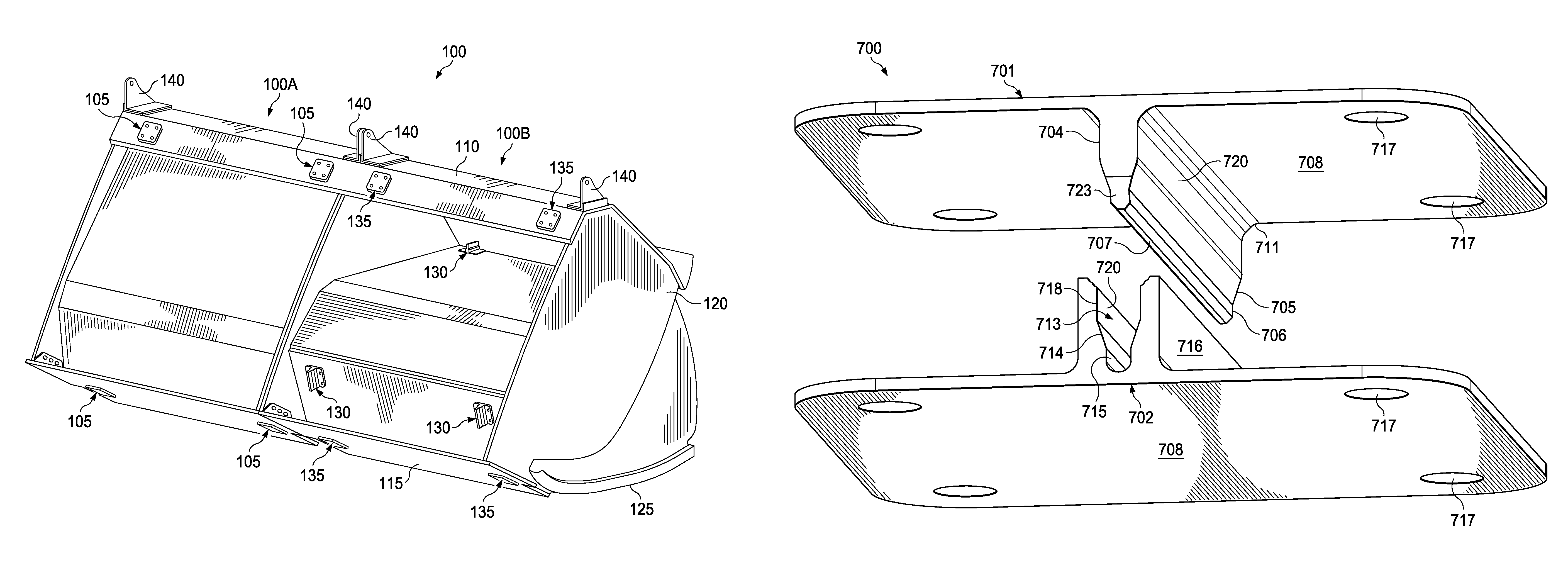
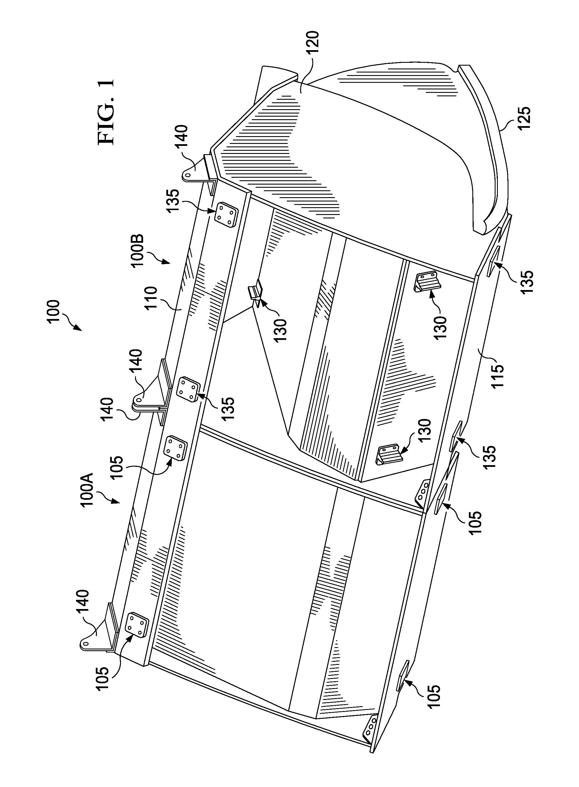
[0032]FIG. 1 is a perspective view of one embodiment of overhead stowage bin assemblies, generally designated by reference number 100 including shear fittings, generally designated by reference number 105. For purposes of illustration in this disclosure, the bin assemblies 100 include first and second bin assemblies 100A and 100B, and are described primari...


PUM


Abstract

An aircraft stowage bin assembly includes shear fittings configured to route a content load from the bucket of the bin assembly to the airframe in the event of a forward load condition, such as a crash or severe turbulence. When the forward inertial load factor on the stowage bin is greater than about 1 g, the shear fittings create an efficient load path from the bucket to the airframe which bypasses the large metallic or composite endframes required by the designs of many conventional overhead stowage bins. As a result, significant reductions in overall bulk and weight, as well as lower manufacturing costs, can be realized.

Description

CROSS-REFERENCED TO RELATED APPLICATIONS[0001]This application is a continuation-in-part of application Ser. No. 11 / 250,689, filed Oct. 14, 2005, status abandoned, and the continuation application filed on Aug. 24, 2009, Ser. No. 12 / 545,957 now U.S. Pat. No. 7,832,685, status allowed.BACKGROUND INFORMATION[0002]1. Field[0003]This disclosure relates generally to stowage bins and, more particularly, to overhead stowage bins in vehicle passenger cabins.[0004]2. Background[0005]Modern passenger airplanes often include overhead stowage bins in the passenger cabin for storage of carry-on luggage and other items. Such bins are often mounted with numerous mountings located along the ceiling and sidewalls of the passenger cabin. These mountings are typically designed to support a predetermined amount of weight within the bins during normal flight conditions. In addition, the mountings are designed to keep the bins securely fastened to the airframe in the event of a crash or severe turbulence...

Claims


Application Information

Patent Timeline
Patent Type & Authority Patents(United States)
IPC IPC(8): B64D9/00
CPCB64D11/003Y02T50/46Y02T50/40
Inventor SCHMITZ, CHAD D.MANHARDT, JOSEPH MATTHIAS
Owner THE BOEING CO
Why Eureka
Try Eureka