Aircraft with active center of gravity control

a technology of center of gravity and aircraft, applied in process and machine control, instruments, navigation instruments, etc., can solve the problems of insufficient to achieve the goal of reducing boom, many of the desirable features of supersonic civilian aircraft, particularly low-boom performance and long range, and difficult to achieve. , the effect of extending the cruise range, reducing travel times, and reducing the number of passengers

Inactive Publication Date: 2005-03-10
SUPERSONIC AEROSPACE INT
View PDF11 Cites 108 Cited by
  • Summary
  • Abstract
  • Description
  • Claims
  • Application Information

AI Technical Summary

Benefits of technology

[0007] What are desired are an aircraft and constituent components that enable supersonic flight by applying new technologies and an innovative aircraft design approach. What is further desired is an aircraft that can significantly reduce travel times, for example by a factor of two through supersonic cruise speed capability, while retaining extending cruise ranges and spacious passenger comfort. In various embodiments, the speed advantage can be achieved with an environmentally-friendly design, compliant with takeoff and landing noise standards, engine emission requirements, and producing a very soft sonic signature during supersonic flight.
[0008] In accordance with some embodiments, a supersonic aircraft comprises a wing, a fuselage, a plurality of fuel tanks contained within the wing and / or fuselage, and a fuel transfer system communicatively coupled to the plurality of fuel tanks and capable of transferring fuel among the plurality of fuel tanks. The aircraft further comprises at least one sensor capable of indicating a flight parameter and a controller. The controller is coupled to the one or more sensors and to the fuel transfer system. The controller can transfer fuel among the plurality of fuel tanks and adjust the aircraft center of gravity to reduce trim drag and increase aircraft range.
[0009] In accordance with other embodiments, an automated fuel transfer system can be used in a supersonic aircraft. The aircraft includes a fuselage and wing. The automated fuel transfer system comprises a plurality of fuel tanks distributed within the wing and / or the fuselage, a plurality of pumps coupled to the plurality of fuel tanks and capable of transferring fuel among the plurality of fuel tanks, at least one sensor capable of indicating a flight parameter, and a controller. The controller is coupled to the sensors and the plurality of pumps, and transfers fuel among the plurality of fuel tanks to modify the aircraft lift distribution, thereby reducing or minimizing aircraft sonic boom.
[0010] According to further embodiments, an aircraft control system is used in a supersonic aircraft. The aircraft includes a fuselage and wing. The control system comprises a plurality of control effectors coupled to the wing, a plurality of fuel tanks distributed within the wings and / or the fuselage, a plurality of pumps coupled to the plurality of fuel tanks and capable of transferring fuel among the plurality of fuel tanks, and a plurality of actuators coupled to the control effectors. The control system further comprises at least one sensor capable of indicating a flight parameter, and at least one vehicle management computer coupled to the at least one sensor, the plurality of pumps, and the plurality of actuators. The vehicle management computer can manage the control effectors and transfer fuel among the plurality of fuel tanks to adjust aircraft trim and center of gravity position to operate the aircraft in at least two flight modes. The variable flight modes have different trim drag and sonic boom performance.

Problems solved by technology

Technology advances have produced longer range, safer, and more comfortable aircraft—but not faster flights.
Many of the desirable features of supersonic civilian aircraft, particularly low-boom performance and long range, are very difficult to attain.
The difficulty of such a result is indicated by the agency's admission that only a revolutionary design will meet the goal, and that incremental application of new technologies, or integration of existing technologies, is expected to be insufficient to attain the reduced boom goal.

Method used


Image

  • Aircraft with active center of gravity control
  • Aircraft with active center of gravity control
  • Aircraft with active center of gravity control

Examples


Embodiment Construction

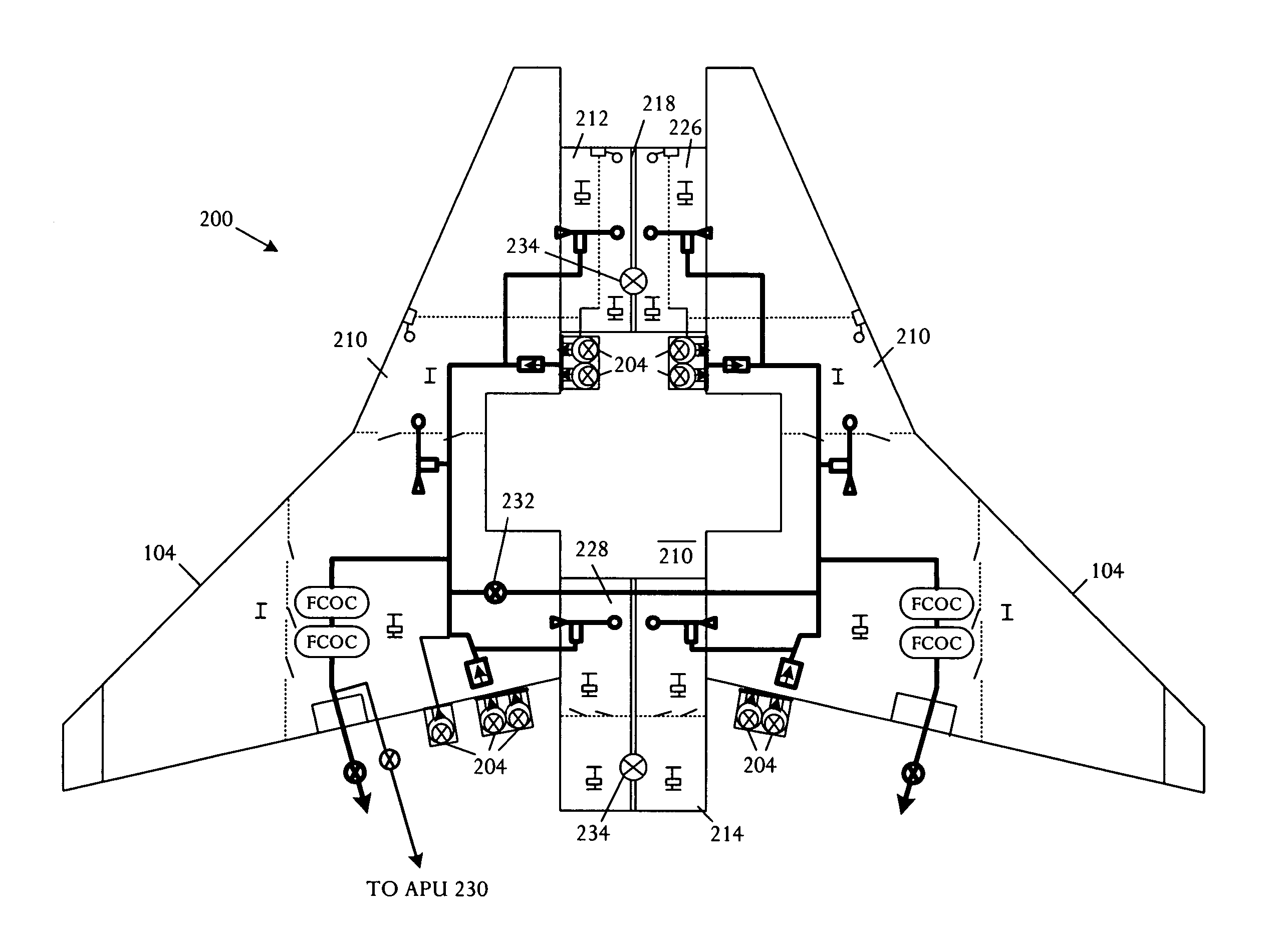
[0024] An aircraft uses a set of sensors to indicate current and projected flight parameters of the aircraft during flight. The parameters are supplied to a computer or controller that executes an optimization algorithm to obtain an appropriate aircraft center of gravity to attain one or more objectives including: (1) reducing trim drag and thereby increase aircraft range, (2) changing the lift distribution to attenuate, reduce, minimize, or otherwise optimize aircraft sonic boom, (3) reducing the trim requirement to increase aircraft controllability, and (4) assisting in maintaining stability during flight. The optimal center of gravity for desired performance is attained by an automated system that actively transfers fuel among multiple aircraft internal fuel tanks.

[0025] Active center of gravity management is desirable, particularly in a supersonic aircraft, since the aircraft's aerodynamic center moves significantly from subsonic to supersonic flight regimes. Automated control ...


PUM


Abstract

A supersonic aircraft comprises a wing, a fuselage, a plurality of fuel tanks contained within the wing and/or fuselage, and a fuel transfer system communicatively coupled to the plurality of fuel tanks and capable of transferring fuel among the plurality of fuel tanks. The aircraft further comprises at least one sensor capable of indicating a flight parameter and a controller. The controller is coupled to the one or more sensors and to the fuel transfer system. The controller can transfer fuel among the plurality of fuel tanks and adjust the aircraft center of gravity to reduce trim drag and increase aircraft range.

Description

BACKGROUND OF THE INVENTION [0001] The global economy makes long range business travel more essential than ever. However, other than Concorde, with presence declining as transatlantic flights have discontinued, the pace of business travel remains at 1960's-era speeds. Technology advances have produced longer range, safer, and more comfortable aircraft—but not faster flights. [0002] Supersonic overland capability and range are drivers of market potential for aircraft in the commercial and business sector. Buyers of supersonic commercial aircraft are expected to be from entities such as corporations, governments and government agencies, and high net-worth individuals. Most operators are expected to be large organizations, for example corporations and governments, with sophisticated flight departments that can manage multiple aircraft types. Flights are expected to depart and arrive in a wide range of environments, from large international and national airports to small local airfields...

Claims


Application Information

Patent Timeline
Patent Type & Authority Applications(United States)
IPC IPC(8): B64C17/10B64C30/00
CPCB64C30/00B64C17/10
Inventor LEE, HOWARDMORGENSTERN, JOHN M.AMINPOUR, HOSSEIN
Owner SUPERSONIC AEROSPACE INT
Why Eureka
Try Eureka