Fixed wing aircraft are restricted to operations from relatively few airports and many of these airports are not their desired destination.
In military applications, airbases are vulnerable to
attack.
The reason this search continues is that the helicopter is full of performance limitations and safety problems.
The performance is limited due to its limited
forward speed due to retreating blade stall.
It also has a limited range due to its inefficiency compared to
fixed wing aircraft.
The limited range is further reduced by the utilization of light weight
turbine engines, which do not reach any reasonable
fuel efficiency until operating at high altitudes where helicopters do not normally operate.
There are many safety related problems that engineers and pilots are fully aware of.
So, the helicopter has been the mainstay solution to our vertical flight needs because we have not found a better solution, but the
aviation industry has not stopped searching for better solutions.
There are a number of different ways to combine vertical flight with the speed and range performance of a conventional
airplane, but developing a practical, redundant, and useful
payload capable
hybrid aircraft has proven to be a surprisingly difficult and elusive task.
Any weight of solely vertical flight mechanisms is useless during
forward flight and represents a reduction in available
payload relative to a
fixed wing aircraft capability.
Any mismatch represents excess capacity which corresponds to
excess weight in one mode of flight.
In fact, there are so many attempted VTOL aircraft solutions to this problem that there simply is not enough room in this
patent application to
list them all and their related problems.
Most were not able to achieve the two main VTOL goals explained earlier.
This craft first flew in 1966 and crashed, on Aug. 8, 1966 due to a single
propeller control failure.
The problem of a failure of a gearbox, shaft, or
propeller and VTOL operation with
airplane speed, range, and payload was not solved by the
ducted propeller or fan design.
Again, the duct gave the added static
thrust efficiency for vertical flight but the extra weight and additional drag was a problem.
The design used
cross coupled drive shafts which significantly increased weight.
The problem of a failure of a gearbox, shaft, or propeller and VTOL operation with
airplane speed, range, and payload was not solved by the
ducted propeller or fan design.
Much of the all important payload capability was consumed by the complex fan
system.
The transitional behavior was reported as quite “abrupt” preventing it from being adequate for “service pilots”.
The problem of a failure of a fan and VTOL operation with airplane speed, payload, and range was not solved by this ducted fan design.
This aircraft had problems with cross-linked
drive shaft vibrations.
It also had problems with wing angles greater than about 35 degrees.
The wake due to wing stall caused serious control problems and as it converted from
forward flight, the increase in wing
angle of attack yielded too much lift and the aircraft climbed.
These behaviors and problems were judged unacceptable.
This aircraft configuration did not solve the problems resulting from the failure of a gearbox, driveshaft or propeller.
This aircraft configuration did not solve the failure of a gearbox, driveshaft or propeller problems.
The VTOL design did not produce a practical aircraft with meaningful payload and range.
The problem of engine failure was not solved by this aircraft design.
The problem of engine failure was not solved by this aircraft design.
VTOL solutions using directed jet thrust will seldom be efficient or inexpensive, certainly not safe.
The problem of a failure of a propulsion unit is not solved by these designs.
The problem of engine failure and useful payload was not solved by this aircraft design.
These versions were built and flown but all test pilots had serious
visibility problems when attempting landings.
They actually accomplished the goal of vertical and horizontal flight using the same equipment and power but were not capable of carrying any real payload other than the
pilot and fuel.
Their propeller disk loadings were simply too great for any meaningful payload and the landing challenge was completely unacceptable for any manned service.
The problem of a failure of a gearbox, shaft, or propeller is not solved by this design.
The prototype encountered significant vibrations during the transition to forward flight.
The problem of a failure of a gearbox, shaft, or propeller / rotor is not solved by this design.
The problem of a failure of a gearbox, shaft, or rotor is not solved by this design.
The problem of a failure of a gearbox, shaft, or rotor is not solved by this design.
This vehicle represents a solution to Tilt Rotor flight, but has been quite costly in terms of development and
unit cost.
This is complex, heavy and expensive.
This may be a reasonable risk to the military, compared to the lives it can save, but may prove problematic and too costly in the commercial market.
1. The failure of either propulsion unit to produce thrust, results in the loss of the aircraft and occupants. The
cross coupled shaft
system provides a marginal performance
backup limited to engine failure, not gearbox or rotor failures. The loss of 50% of this aircraft's power results in its' inability to continue its' mission and in many circumstances requires immediate landing. The present invention solves this problem with its' fundamental design, providing for continued flight following the complete loss of thrust by any propulsion unit, no matter what the cause.
2. Inability to use evasive maneuvering tactics to avoid hostile fire, similar to that found in high
threat landing zones. Quick maneuvering has resulted in the
cracking and breaking of rotor root components which may result in the loss of a blade, and therefore the aircraft. The 38 foot rotors are limited to about 10 degree
flapping angles. Quick maneuvering can (and has) easily exceed this angle resulting in the failure of a rotor and the potential loss of the aircraft. This limited maneuverability might be acceptable for commercial operations, but not for the intended applications of the military. The V22 is intended for
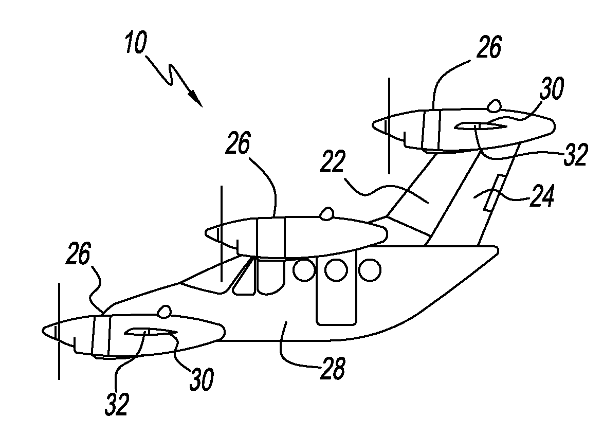
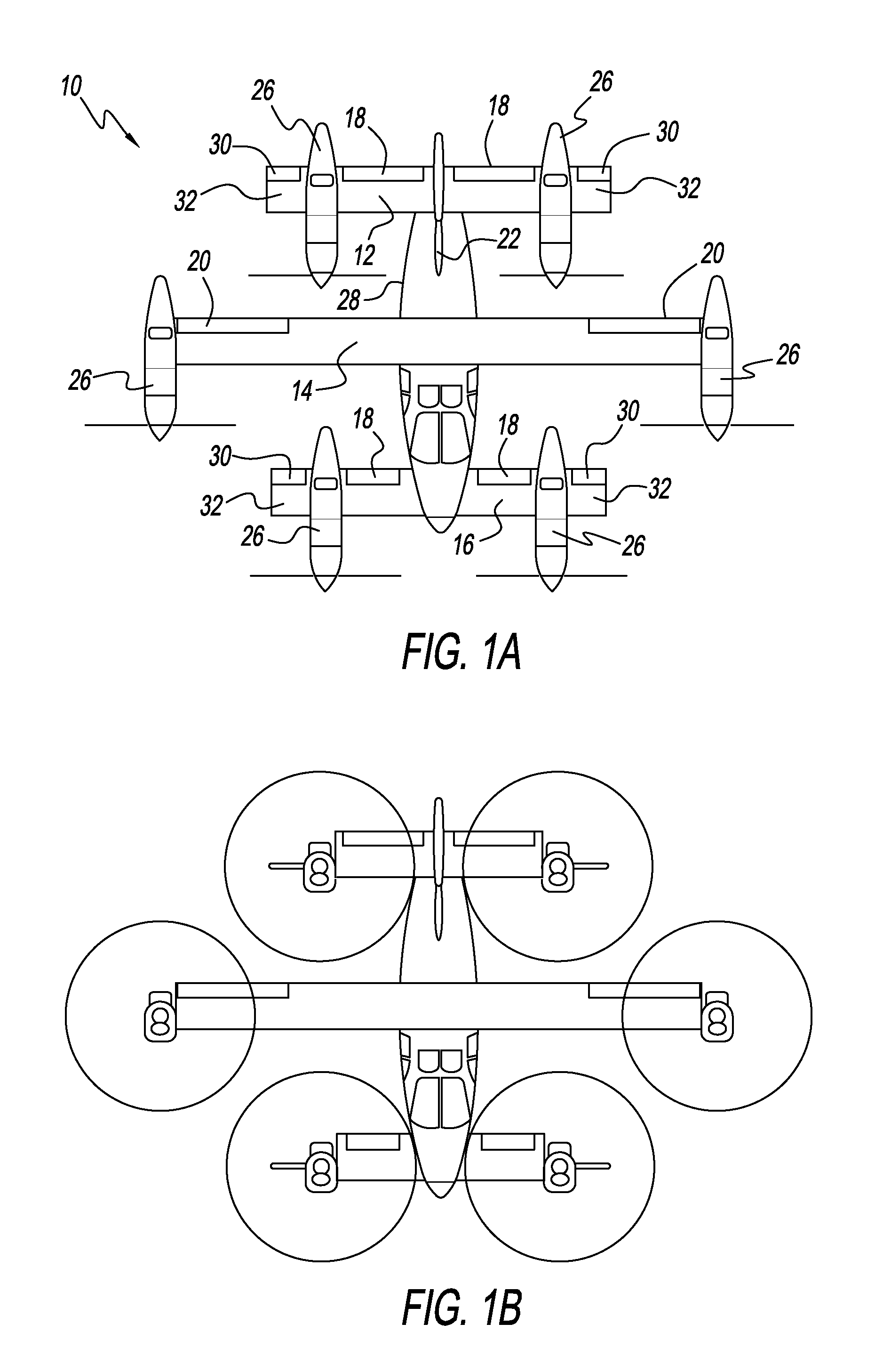
insertion and extraction missions during ground fire. The present invention solves this problem by using much smaller
diameter rigid propellers as opposed to helicopter like rotors which allow the blades to flap and distribute the load to six propellers instead of two rotors. The propellers are smaller for the same
disk loading, therefore they have a smaller
moment of inertia. Propellers have been used successfully on aerobatic airplanes and WWII dog fighters without blade separation due to these high gyroscopic forces. For example, the V22 Osprey has two rotors totaling a disk area of 2,268 square feet. Each blade is roughly 19 feet long (including hub
radius), the length of a blade in a six propeller
system of the same area would be eleven feet. This represents a significant reduction in blade root forces due to high G maneuvers.
3. Limited center of gravity (c.g.) range. The V22 design is inherently a narrow C.G. aircraft. The side by side location of the rotors does nothing to improve longitudinal c.g. range and the V22 has the highly limited c.g. range of a helicopter with a single rotor. It was intended that soldiers “down
rope” from the left and right side of the V22, but the rotor wash blew them off the ropes due to the hurricane like wind below the rotors. A single
rope was attached below the
tail above the rear ramp area avoiding the rotor wash. This limited C.G. range prevents soldiers from moving to the rear ramp during “down roping” insertions, until the previous two have released the ropes' end at the ground. This significantly increases the time required to down
rope 25 marines exposing the V22 to hostile ground fire for an unusually long period. If soldiers are excited and rush to the rear of this craft exceeding its aft C.G. limit, control will be lost along with the aircraft. The present invention solves this problem by distributing the thrust around the aircraft. The C.G. range is quite large and is therefore very tolerant of moving payload.
4.
Settling with power or Vortex Ring State (VRS) is a well known (by engineers and pilots) problem with helicopters. It is a condition where an annulus or “donut” of accelerated air is created around the
actuator (rotor) disk. Simply put, it's what happens when you try and fly in your own rotor wake. Roughly speaking, the air is turbulent and you begin to lose lift, if you raise the collective (increasing
pitch) to correct the situation, it becomes worse. It is similar to running up the down escalator. The solution has been to reduce collective and push the cyclic forward to fly out of the disturbed air. An accepted method to avoid it is, as an example, is not to descend more than 300 fpm if you are flying less than 30 kts. When a helicopter gets in this situation, it can recover as long as it has enough altitude. Even tandem rotor helicopters can experience this behavior. The front rotor normally enters VRS first causing the front to drop, assisting in the necessary forward motion for
recovery. The V22 configuration is different. When one of its rotors enters VRS, the aircraft begins to roll, the
pilot instinctively corrects with opposite stick, worsening the problem and the ship rolls over and plunges toward the ground. This is what happened near Tucson, Ariz. on a simulated night mission killing many Marines. The present invention solves the VRS susceptibility problem for Tilt
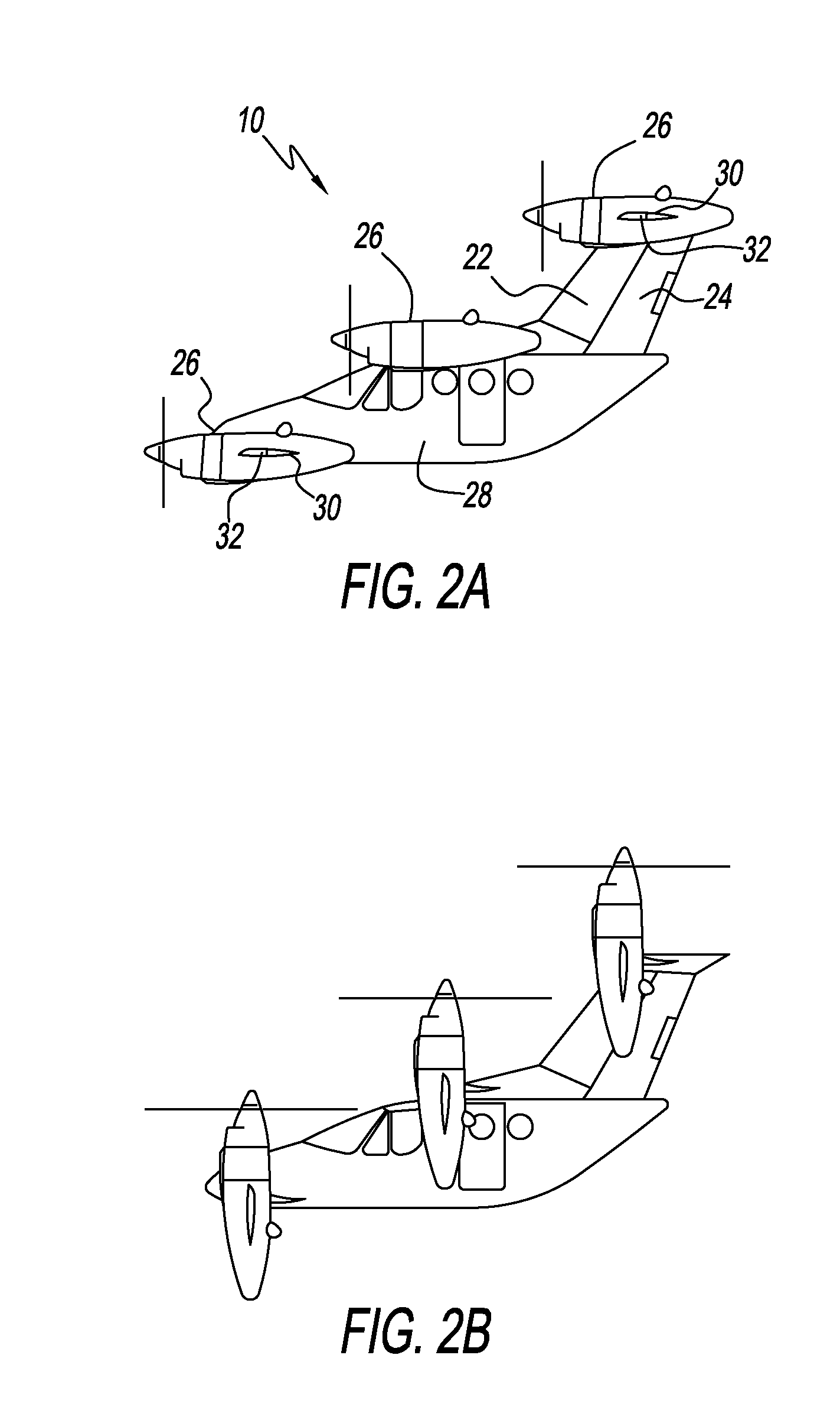
Propeller configurations by distributing the load among six propellers. When a propeller enters VRS the present invention should remain stable and controllable.

