
MIS crosslink apparatus and methods for spinal implant

a cross-link device and cross-link technology, applied in the field of spinal implants, can solve the problems of inflexible cross-link devices, many weaknesses of conventional cross-link devices, and inability to provide a wide range of motion, and achieve the effect of increasing rigidity

Active Publication Date: 2011-11-01
ZIMMER BIOMET SPINE INC
View PDF72 Cites 50 Cited by
  • Summary
  • Abstract
  • Description
  • Claims
  • Application Information

AI Technical Summary

Benefits of technology

"The present disclosure is about a method for stabilizing a spine using minimally invasive surgery. The method involves guiding a fixed portion of a cross-link to a vertebra on the first side of the spine, connecting it to an elongated member, guiding an adjustable portion of the cross-link to a vertebra on the second side of the spine, connecting it to the elongated member, and advancing the cross-link a selected distance in the adjustable portion. The method also includes engaging one or more engagement features to couple the adjustable portion and the fixed portion. The technical effects of this method include minimizing damage to the spine, reducing the duration of the surgery, and providing stability to the spine."

Problems solved by technology

The rods usually do not provide much protection against torsional forces or movement.
Conventional cross-link devices, however, have many weaknesses.
For example, conventional cross-link devices are inflexible and provide a very limited range of motion.
Thus, a surgeon using conventional cross-link devices cannot readily adjust the spinal implant according to each patient's needs and anatomy.
Furthermore, because a surgeon has to adjust a relatively large number of fasteners during the surgery, the installation of a conventional cross-link device can be time consuming, which is highly undesirable.

Method used


Image

  • MIS crosslink apparatus and methods for spinal implant
  • MIS crosslink apparatus and methods for spinal implant
  • MIS crosslink apparatus and methods for spinal implant

Examples


Embodiment Construction

[0112]The disclosure and the various features and advantageous details thereof are explained more fully with reference to the non-limiting embodiments that are illustrated in the accompanying drawings and detailed in the following description. Descriptions of well known starting materials, processing techniques, components and equipment are omitted so as not to unnecessarily obscure the disclosure in detail. Skilled artisans should understand, however, that the detailed description and the specific examples, while disclosing preferred embodiments of the disclosure, are given by way of illustration only and not by way of limitation. Various substitutions, modifications, additions or rearrangements within the scope of the underlying inventive concept(s) will become apparent to those skilled in the art after reading this disclosure.

[0113]A spinal stabilization system may be installed in a patient to stabilize a portion of a spine. Spinal stabilization may be used, but is not limited to...


PUM


Abstract

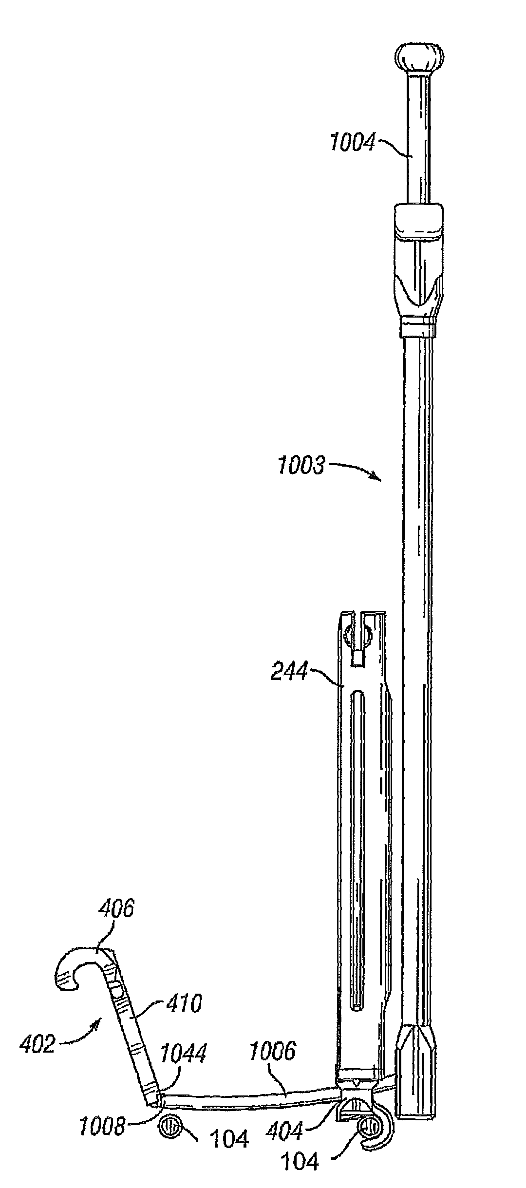
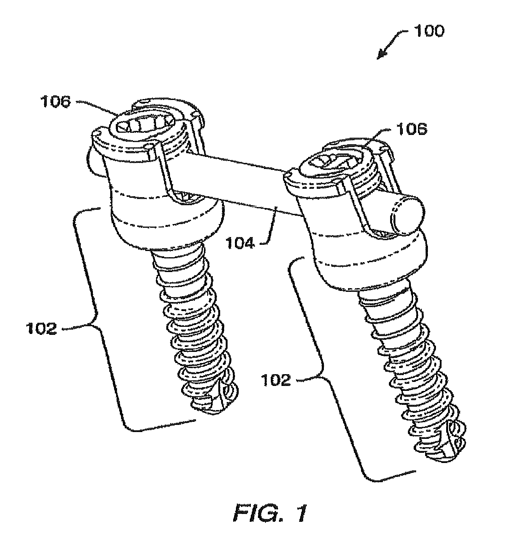
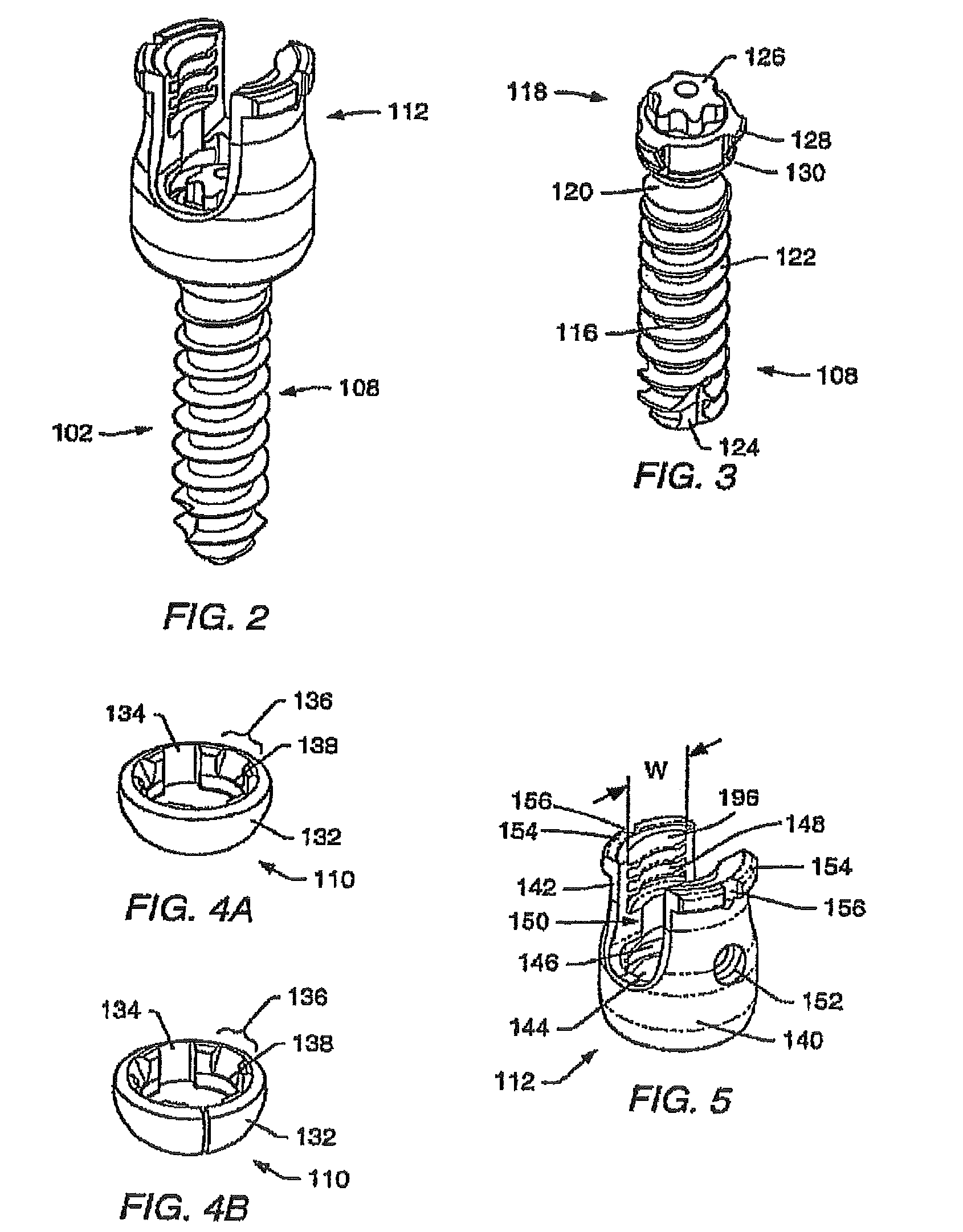
A spinal implant provides support for desired parts of the spine. The implant can provide support in fusion situations. The spinal implant includes a pair of elongated members and a variable length cross-link. A variable length cross-link apparatus may couple to the first and second elongated members. Each variable length cross-link device may include a fixed portion having a receiver portion for attachment to a first elongated member. Each variable length cross-link may include a transverse portion. Each variable length cross-link may include an adjustable portion having a receiver portion for attachment to a second elongated member and a transverse portion engaging member. Inserting the transverse portion of the fixed portion into the engaging portion of the adjustable portion may form a cross-link for stabilizing motion between two elongated members. Engaging the adjustable portion at a selected point on the transverse portion establishes a length selected by the surgeon. The surgical procedure may use minimally invasive surgery or non-minimally invasive surgery, as desired. Components of the system may be inserted through sleeves attached to various coupling devices, or may be inserted and guided along wires at more lateral angles.

Description

TECHNICAL FIELD OF THE DISCLOSURE[0001]The present disclosure relates generally to spinal implants. More particularly, the disclosure concerns articulating variable cross-link or transverse connecting devices useful in spinal implants.BACKGROUND OF THE DISCLOSURE[0002]Modern spine surgery often involves the use of spinal implants to correct or treat various spine disorders and / or to support the spine. Spinal implants may help, for example, to stabilize the spine, correct deformities of the spine, facilitate fusion, or treat spinal fractures. Typical spinal implants may include rigid (i.e., via a fusion procedure) support for the affected regions of the spine. Such spinal implants limit movement in the affected regions (e.g., in a fused region) in virtually all directions.[0003]Prior spinal implants typically use elongated members to support parts of the spine. The rods usually do not provide much protection against torsional forces or movement. Efforts have been made to address that...

Claims


Application Information

Patent Timeline
Patent Type & Authority Patents(United States)
IPC IPC(8): A61B17/70
CPCA61B17/1655A61B17/1671A61B17/7032A61B17/7037A61B17/7052A61B17/7082A61B17/7083A61B17/7085A61B17/7091A61B17/1637A61B17/7034A61B2019/307A61B2019/461Y10S606/914A61B2090/037A61B2090/061
Inventor FORTON, CHARLES R.BERGERON, BRIAN J.ELY, KAMERON SCOTT
Owner ZIMMER BIOMET SPINE INC
Learn More