Cylindrical nickel-zinc cell with negative can

a nickel-zinc cell and cylindrical technology, applied in the field of cylindrical nickel-zinc cells, can solve problems such as cell damag

Active Publication Date: 2011-11-01
ZINCFIVE POWER INC
View PDF114 Cites 9 Cited by
  • Summary
  • Abstract
  • Description
  • Claims
  • Application Information

AI Technical Summary

Problems solved by technology

However, as mentioned above, a corrosive reaction between zinc and the can material can cause damage to the cell.

Method used


Image

  • Cylindrical nickel-zinc cell with negative can
  • Cylindrical nickel-zinc cell with negative can
  • Cylindrical nickel-zinc cell with negative can

Examples


Embodiment Construction

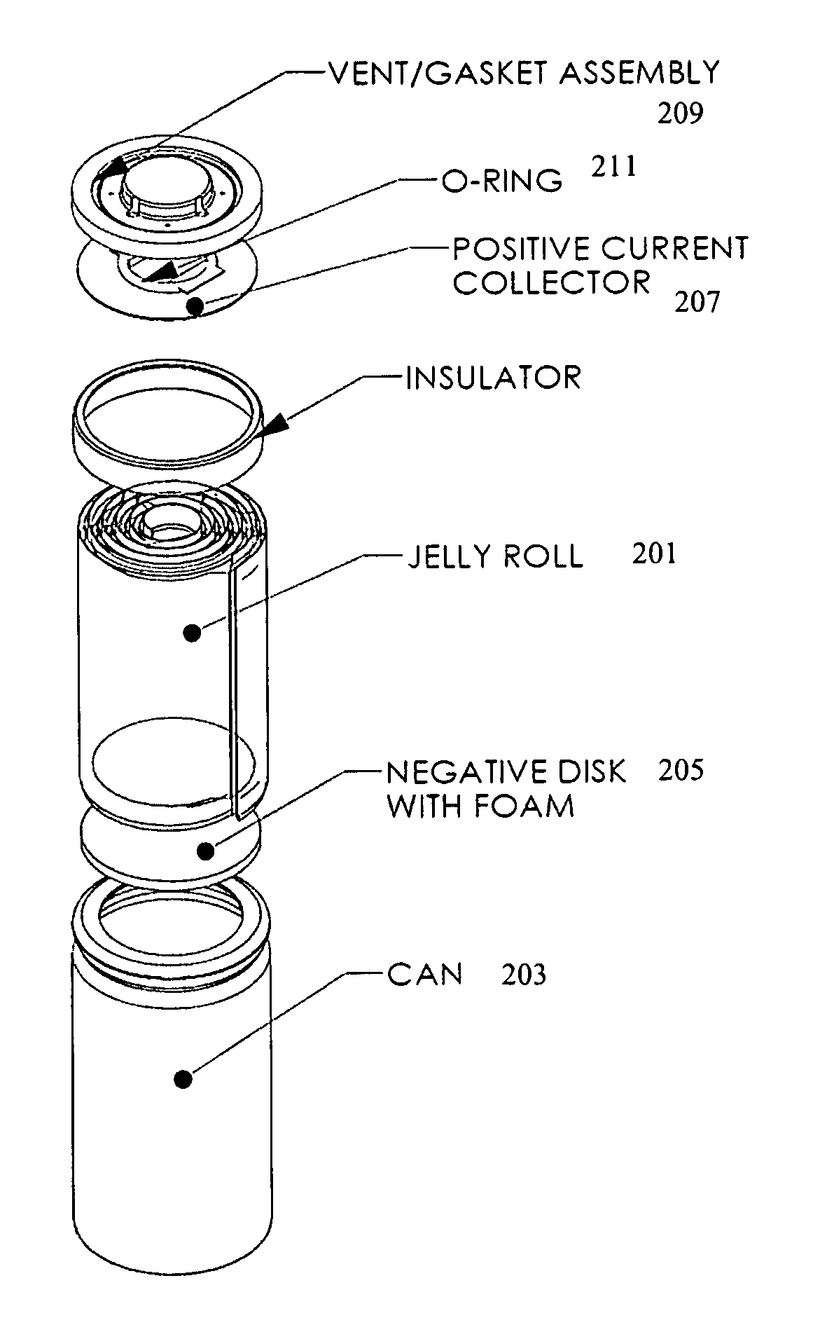
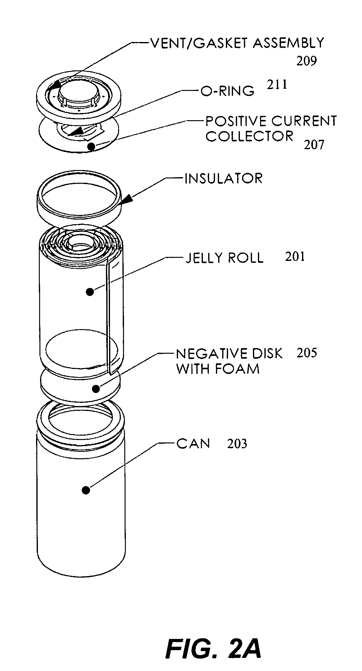
[0018]Embodiments of the present invention are described herein in the context of design and manufacturing a nickel-zinc cell. Those of ordinary skill in the art will realize that the following detailed description of the present invention is illustrative only and is not intended to be in any way limiting. Other embodiments of the present invention will readily suggest themselves to such skilled persons having the benefit of this disclosure. For example, anticorrosion material may be applied to the inside of the cell can using other procedures.

[0019]Reference will be made in detail to implementations of the present invention as illustrated in the accompanying drawings. In this application, the terms “battery” and “cell” may be used interchangeably, such use should be clear from the context of the discussion.

Introduction

[0020]The recent trend for portable devices has increased the needs and requirements for environmentally friendly rechargeable batteries suitable for use for consumer...


PUM

PropertyMeasurementUnit
pore sizeaaaaaaaaaa
pore sizeaaaaaaaaaa
temperatureaaaaaaaaaa

Abstract

A nickel-zinc battery cell is formed with a negative can, a positive cap, and a jelly roll of electrochemically active positive and negative materials within. The inner surface of the can is protected with an anticorrosive material that may be coated or plated onto the can. Good electrical contact between the jelly roll and the cap is achieved through folding the nickel substrate over to contact a positive current collection disk.

Description

CROSS-REFERENCE TO RELATED APPLICATIONS[0001]This application claims priority under U.S.C. §119 to provisional application 61 / 041,891, titled “Cylindrical Nickel-Zinc Cell With Negative Can,” filed on Apr. 2, 2008, and under U.S.C. §120 to application to 11 / 116,113, titled “Nickel Zinc Battery Design,” filed Apr. 25, 2005, the disclosures of which are incorporated herein in their entireties for all purposes.FIELD OF INVENTION[0002]This invention pertains generally to nickel-zinc batteries. More specifically, this invention pertains to the physical design and construction of a cylindrical nickel-zinc cell.BACKGROUND[0003]The recent trend for portable devices has increased the needs and requirements for environmentally friendly rechargeable batteries suitable for use for consumers as a replacement to primary, or not rechargeable, batteries. A conventional rechargeable alkaline battery, e.g., nickel-metal hydride or nickel cadmium, has a negative can and a positive cap. Cylindrical nic...

Claims


Application Information

Patent Timeline
Patent Type & Authority Patents(United States)
IPC IPC(8): H01M2/02H01M2/00H01M2/12H01M6/04H01M50/119H01M50/124H01M50/145H01M50/571
CPCH01M2/0272H01M2/0275H01M2/0277H01M2/0285H01M2/263H01M4/38H01M4/661H01M4/808H01M10/0481H01M10/286H01M10/30C02F2301/063Y02E60/124H01M2/0287H01M2/0292H01M2/022Y02E60/10H01M50/107H01M50/1243H01M50/124H01M50/1245Y02P70/50H01M50/145H01M50/119C23F11/00H01M10/34H01M50/571
Inventor PHILLIPS, JEFFREYKRUGER, FRANZ JOSEFMOHANTA, SAMARESHCLINTON, SEANRIMANOSKY, ERNEST M.ZHAO, JASONMASKE, CECILIAFAN, ZHENG GANG
Owner ZINCFIVE POWER INC
Why Eureka
Try Eureka