Switchable balanced amplifier

a balanced amplifier and switchable technology, applied in the field of electrical circuits and systems, can solve the problems of adding to the size and complexity of the circuit, complicated and lossy input and output path switching or load line switching,

Active Publication Date: 2011-11-01
SKYWORKS SOLUTIONS INC
View PDF1 Cites 4 Cited by
  • Summary
  • Abstract
  • Description
  • Claims
  • Application Information

AI Technical Summary

Problems solved by technology

Conventional solutions for using a single balanced amplifier in multiple modes, operating frequency bands, power settings or applications can require complicated and lossy input and output path switching or load line switching.
This adds to the size and complexity of the circuit, which is often undesirable.

Method used


Image

  • Switchable balanced amplifier
  • Switchable balanced amplifier
  • Switchable balanced amplifier

Examples


Embodiment Construction

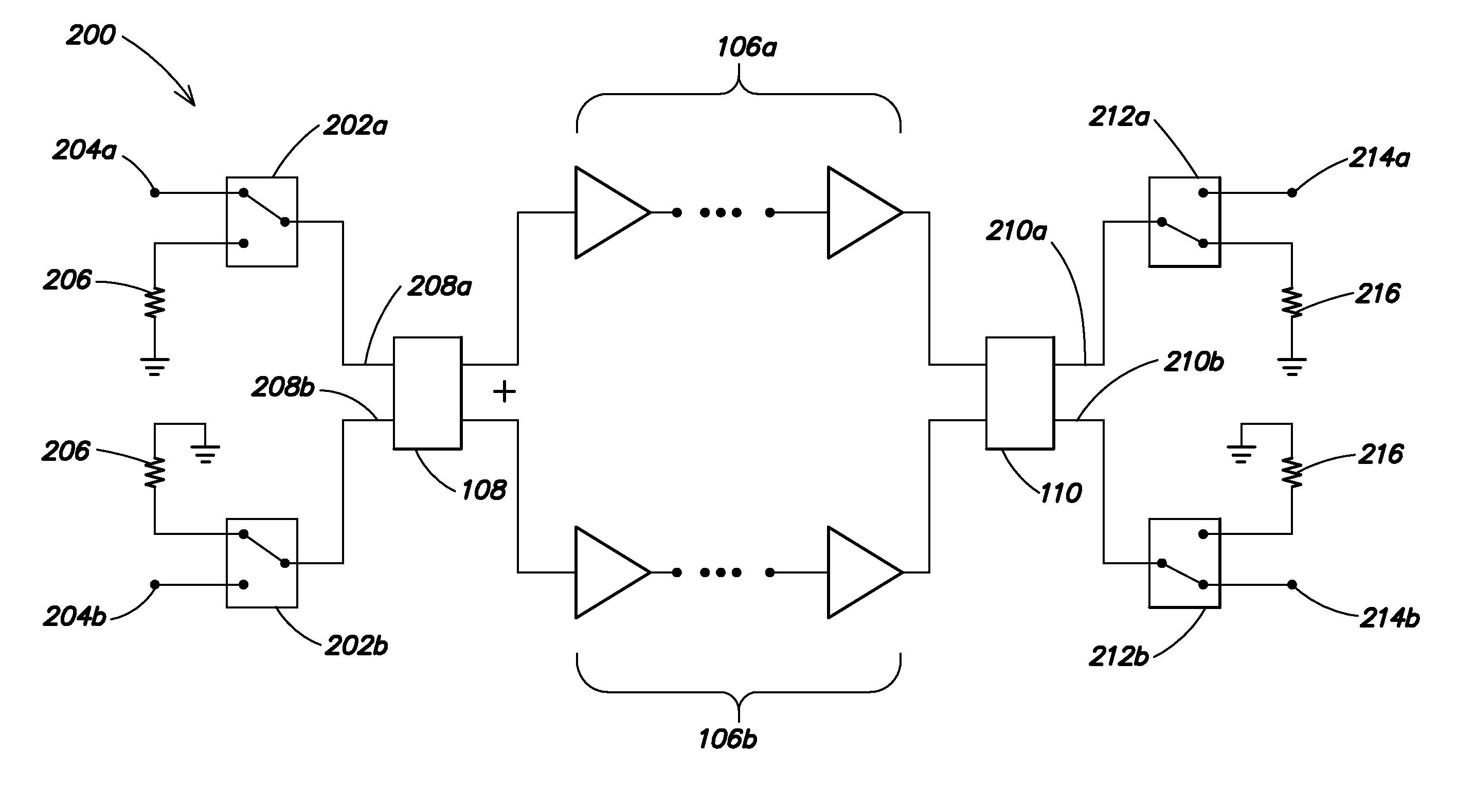
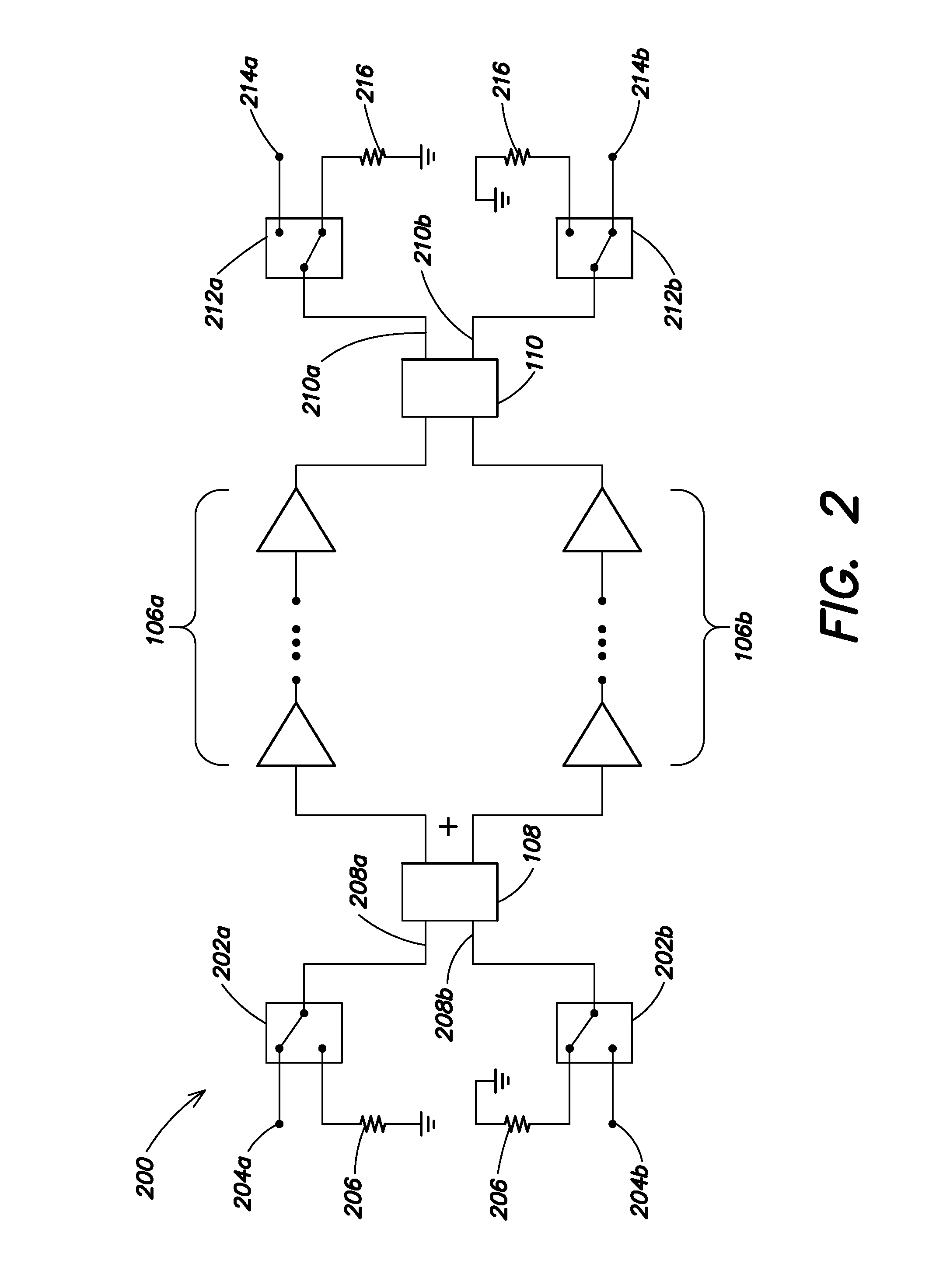
[0026]In many industries, including the wireless communications industry, there is an ever-present drive toward smaller and more complex devices such as, for example, smaller cellular telephones, computers or personal digital assistants (PDAs) that have more features and capability. In these and other applications, it may be desirable for a single component, such as an amplifier, to be capable of different operating characteristics to accommodate different operating modes and / or operating frequency bands of the device in which it is used. Accordingly, aspects and embodiments are directed to a balanced amplifier with configurable input port and output port characteristics. As discussed in further detail below, in one embodiment a “switchable” balanced amplifier is configurable to have different, separate output ports to achieve, for example, different load lines and / or different output power characteristics. In another embodiment, a switchable balanced amplifier has configurable inpu...


PUM


Abstract

A switchable balanced amplifier having multiple, configurable independent input / output paths. Switching networks coupled to the input and / or output quadrature couplers of the balanced amplifier are used to configurably direct any of one or more input signals to any of one or more output ports. In one example, each output port is coupled to circuitry tailored to a specific type of input signal, operating protocol and / or operating frequency band.

Description

CROSS REFERENCE TO RELATED APPLICATIONS[0001]This application claims priority to co-pending U.S. Provisional Patent Application No. 60 / 958,628 entitled “SWITCHABLE BALANCED AMPLIFIER,” filed Jul. 7, 2007, which is incorporated herein by reference in its entirety.BACKGROUND[0002]1. Field of Invention[0003]The present invention relates generally to electrical circuits and systems and, more particularly, to balanced amplifier circuits.[0004]2. Discussion of Related Art[0005]A balanced amplifier typically has one input port and one output port. For example, referring to FIG. 1, there is illustrated an example of a conventional balanced amplifier having a single radio frequency (RF) input 102 and a single RF output 104. The balanced amplifier comprises two chains of amplifiers 106a and 106b that are run in quadrature, that is, operating 90 degrees apart in phase. A quadrature coupler (or splitter) 108 on the RF input 102 phase-shifts the signal 90 degrees at the amplifier inputs, and a s...

Claims


Application Information

Patent Timeline
Patent Type & Authority Patents(United States)
IPC IPC(8): H03F3/68
CPCH03F3/211H03F3/68H03F3/72H03F3/602H03F2200/111H03F2200/192H03F2200/204H03F2203/21109H03F2203/21145H03F2203/7209
Inventor WYSE, RUSSELLYOUNG, JAMES P.
Owner SKYWORKS SOLUTIONS INC
Why Eureka
Try Eureka