
High speed power line network connector and method for power line networking

a high-speed power line and network connector technology, applied in powerline communication applications, data switching networks, frequency-division multiplexes, etc., can solve the problems of data loss, many limitations still exist, poor physical connection of power line communication, etc., to improve connectivity, selective connection, and easy implementation

Inactive Publication Date: 2011-11-01
ASOKA USA CORP
View PDF7 Cites 0 Cited by
  • Summary
  • Abstract
  • Description
  • Claims
  • Application Information

AI Technical Summary

Benefits of technology

"The present invention provides techniques for power line networking, which can be applied in various networking environments such as buildings, homes, and apartments. The invention provides a power line module that can be easily inserted into a power outlet and connected to a local area network. The power line module has a housing with a power line chip and a coupling device for connecting to the network. The invention also provides a power line gateway device with a housing and a power line module for connecting to the network. The invention can transfer power line signals with a high data rate of up to 80 Mega bits per second over a coupling device and has low resistance to improve connectivity and minimize data loss. The invention is easy to implement and can be selectively connected to users. Overall, the invention provides improved connectivity and speed for power line networking."

Problems solved by technology

Although power line communications have been successful in part, many limitations still exist.
For example, power line communication generally has poor physical connections.
Such resistances often cause data loss, and other network communication problems.
As network communication speeds increase, it becomes more and more difficult to provide proper connectivity using conventional AC outlets and power plugs.

Method used


Image

  • High speed power line network connector and method for power line networking
  • High speed power line network connector and method for power line networking
  • High speed power line network connector and method for power line networking

Examples


Embodiment Construction

[0023]According to the present invention, techniques for power line networking techniques are provided. More particularly, the invention provides a method and system for a high speed power line network using a connector method and device of a determined resistance and less. Merely by way of example, the invention has been applied in a local area network environment, but it would be recognized that other applications exist. The invention can also be applied to building area networking, home networking, office networking, apartments, any combination of these, and other networking applications.

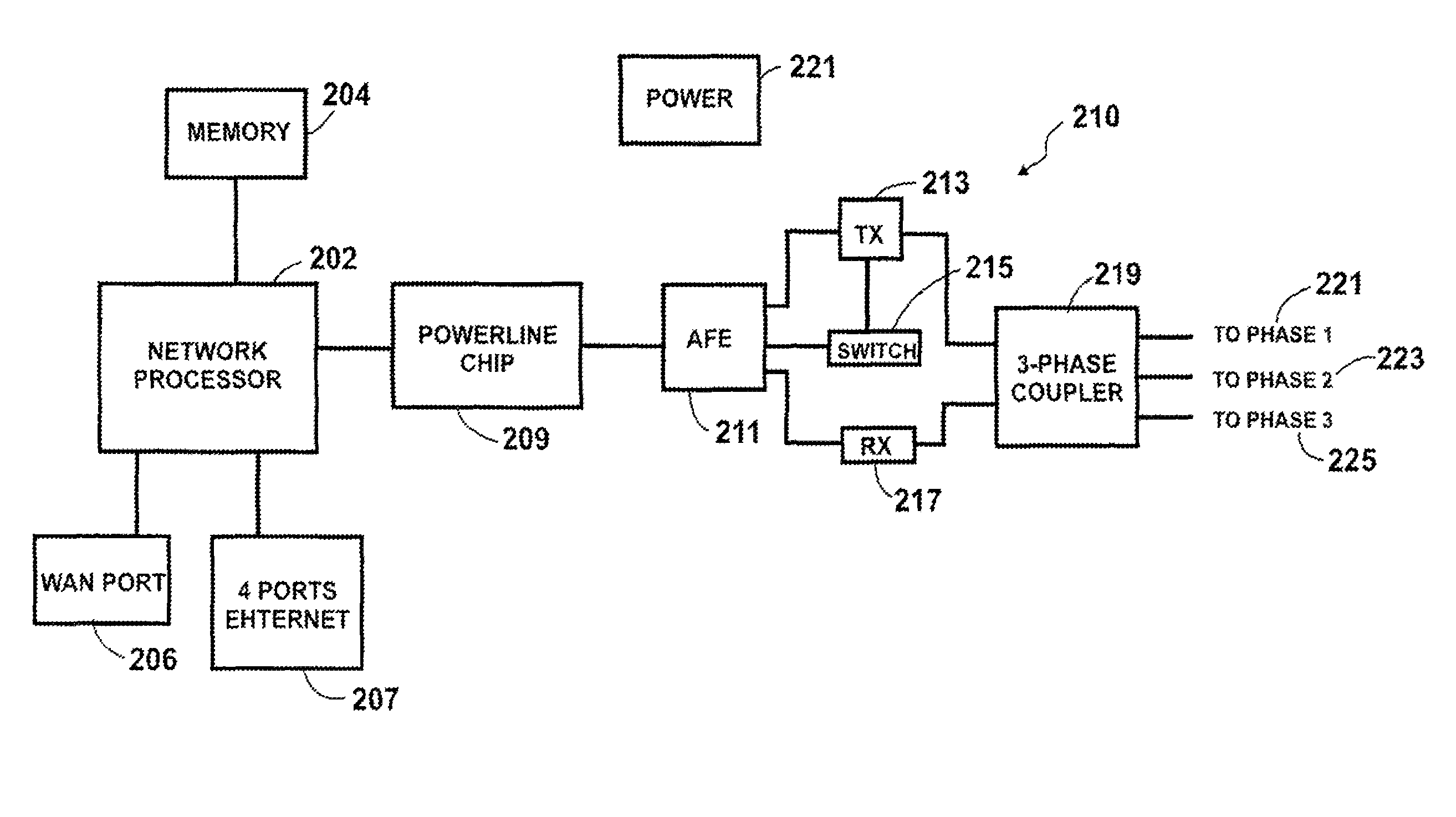
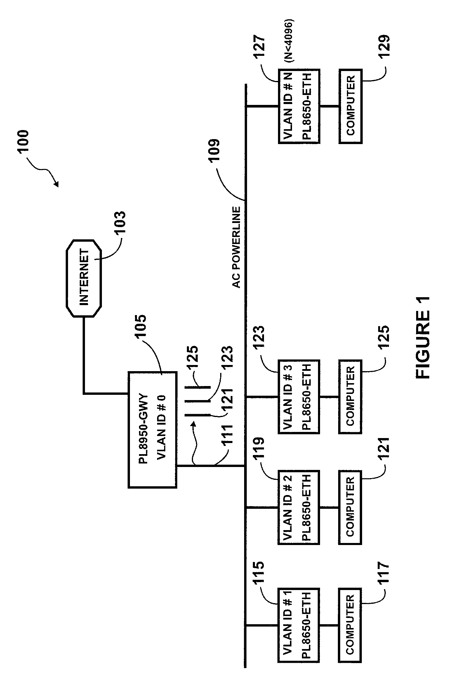
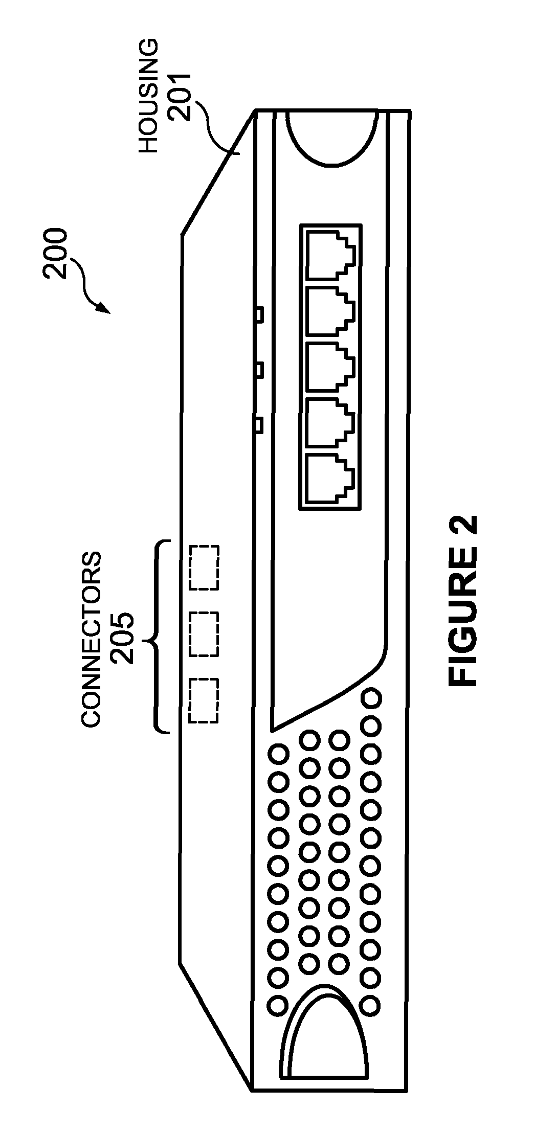
[0024]FIG. 1 is a simplified diagram of a power line system according to an embodiment of the present invention. This diagram is merely an example, which should not unduly limit the scope of the claims herein. One of ordinary skill in the art would recognize many variations, alternatives, and modifications. As shown, the system 100 for power line networking is included. The system 100 has an exte...


PUM


Abstract

A power line module and method. In a preferred embodiment, the power line module is adapted to couple to a power line outlet, which is provided on a power line network within a spatial region. A power line chip is within a housing. In a preferred embodiment. the power line chip has an input / output port and is capable of converting a power line telecommunication signal having a data rate of greater than about 80 Megabits per second from the power line network to an Ethernet signal for use in a local area network segment. The module has a coupling device coupled to the input / output port of the power line chip. In a preferred embodiment, the module has a first pin comprising a plurality of first spring members operably coupled the coupling device. The first pin is insertable into a first site of the power outlet. The module has a second pin comprising a plurality of second spring members operably coupled to the coupling device.

Description

CROSS-REFERENCES TO RELATED APPLICATIONS[0001]This application claims priority to U.S. Provisional Application No. 60 / 824,000, filed Aug. 30, 2006, which is incorporated by reference herein.BACKGROUND OF THE INVENTION[0002]The present invention relates generally to power line networking techniques. More particularly, the invention provides a method and system for a high speed power line network using a connector method and device of a determined resistance and less. Merely by way of example, the invention has been applied in a local area network environment, but it would be recognized that other applications exist. The invention can also be applied to building area networking, home networking, office networking, apartments, any combination of these, and other networking applications.[0003]Telecommunication techniques have been around for numerous years. In the early days, a communication technique known as telegraph was developed. Telegraph generally transferred information from one...

Claims


Application Information

Patent Timeline
Patent Type & Authority Patents(United States)
IPC IPC(8): H04L12/56
CPCH04B3/542H04B2203/5445H04B2203/5466
Inventor CHAN, TAT KEUNG
Owner ASOKA USA CORP
Learn More