Particulate filter regenerating system

a technology of regenerating system and particle filter, which is applied in the direction of machine/engine, electrical control, separation process, etc., can solve the problems of deteriorating fuel economy performance and increasing total fuel consumption, and achieve the effect of suppressing fuel consumption

Inactive Publication Date: 2011-11-08
MAZDA MOTOR CORP
View PDF23 Cites 1 Cited by
  • Summary
  • Abstract
  • Description
  • Claims
  • Application Information

AI Technical Summary

Benefits of technology

[0009]In view of the above circumstances, it is an object of the present invention to provide a particulate filter regenerating system capable of adequately burning and removing PM deposited in a particulate filter, by means of a post-injection of fuel, while effectively suppressing a fuel consumption due to the post-injection.

Problems solved by technology

However, in the later-stage regeneration mode where the post-injection amount is reduced (or the post-injection timing is advanced), although an excessive rise in exhaust gas temperature can be suppressed, a PM burning rate becomes lower along with a reduction in exhaust gas temperature, and thereby, if the later-stage regeneration mode is continued until PM deposited in the filter is completely burned and removed, a process time in the later-stage regeneration mode is increased to cause an increase in total fuel consumption due to the post-injection, which is likely to result in deterioration in fuel economy performance.

Method used


Image

  • Particulate filter regenerating system
  • Particulate filter regenerating system
  • Particulate filter regenerating system

Examples


Embodiment Construction

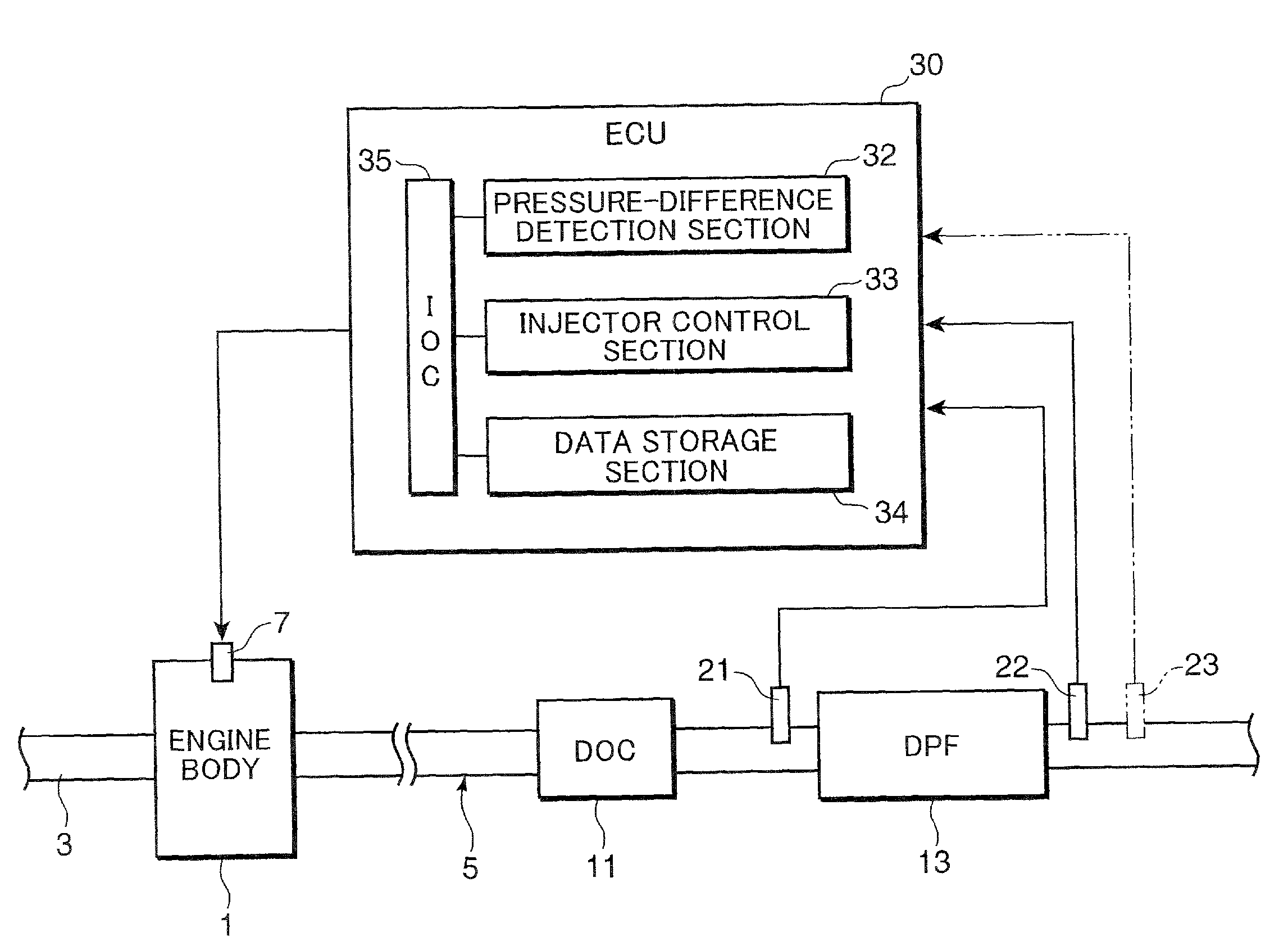
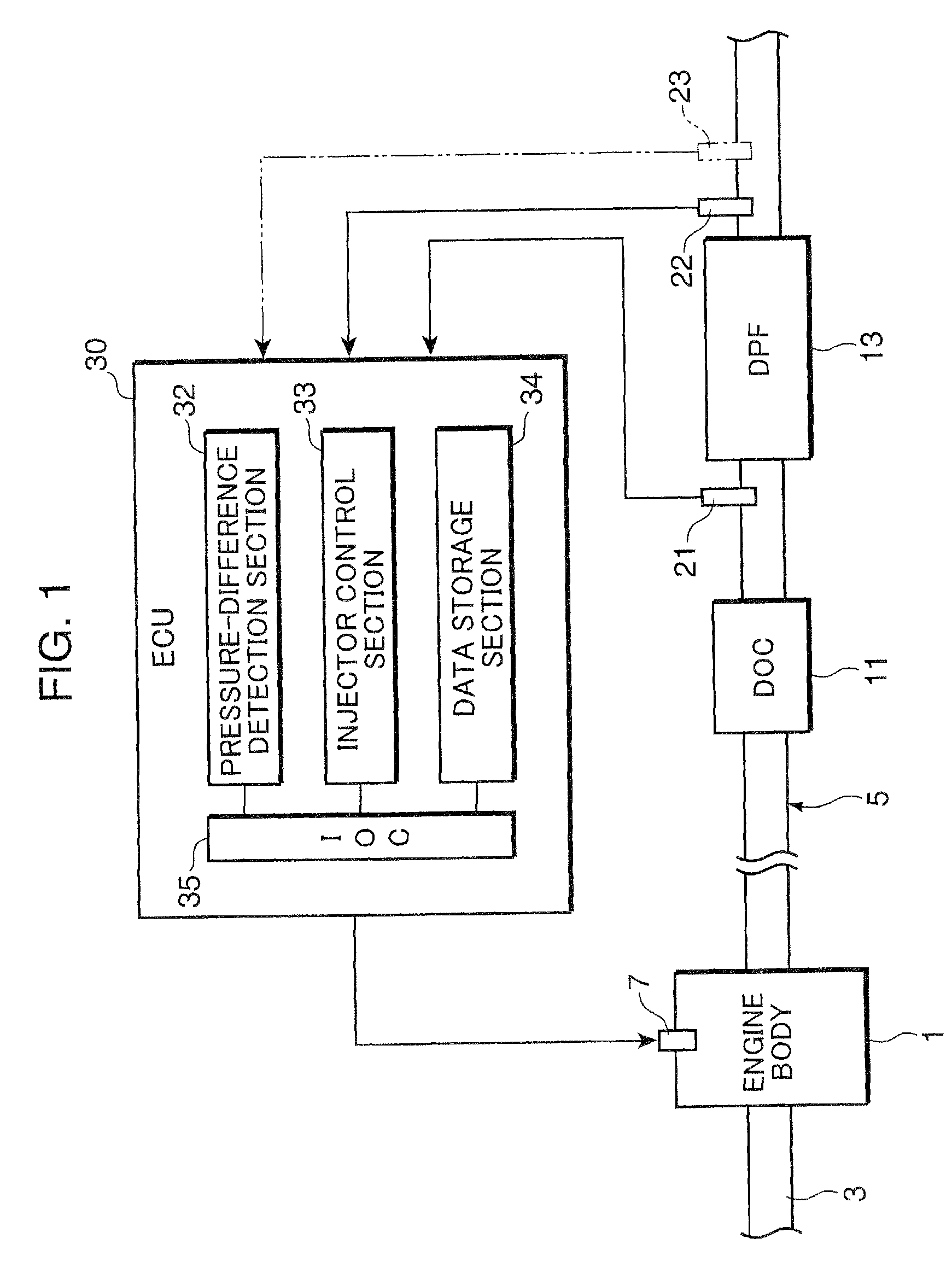
[0017]FIG. 1 is a schematic diagram showing a general configuration of an engine employing a particulate filter regenerating system according to one embodiment of the present invention. The engine illustrated in FIG. 1 comprises an engine body 1 having a piston and a cylinder, an intake passage 3 for supplying combustion air to the engine body 1 therethrough, and an exhaust passage 5 serving as a passage for exhaust gas discharged from the engine body 1. The engine body 1 is provided with an injector 7 (which corresponds to a fuel injection device set forth in the appended claims) adapted to inject fuel supplied from a fuel tank (not shown), directly into a combustion chamber of the engine body 1. This embodiment will be described on an assumption that the engine is a diesel engine, and thereby the injector 7 is adapted to inject light oil as fuel therefrom.

[0018]A diesel oxidation catalyst (oxidation catalyst) 11 and a diesel particulate filter (particulate filter) 13 are interpose...


PUM

PropertyMeasurementUnit
temperatureaaaaaaaaaa
exhaust gas temperatureaaaaaaaaaa
gas temperatureaaaaaaaaaa

Abstract

Disclosed is a particulate filter regenerating system which comprises a fuel injection device (7) adapted to inject fuel into a combustion chamber of an engine body (1), and an exhaust gas temperature-adjusting device (33) adapted, when a PM deposit amount which is an amount of particulate matter (PM) deposited in a DPF (particulate filter) 13 provided in an exhaust passage of an engine, reaches a predetermined value X, to cause the fuel injection device (7) to perform a post-injection for injecting fuel into the combustion chamber during an expansion stroke of the engine, so as to execute a filter regeneration process of raising a temperature of exhaust gas flowing into the DPF 13 to burn the deposited PM. The exhaust gas temperature-adjusting device (33) is operable to cause the fuel injection device (7) to stop performing the post-injection in a stage where a PM burning amount which is an amount of PM burned through the filter regeneration process, is less than an initial PM deposit amount which is the PM deposit amount X at a timing of initiation of the filter regeneration process, by a predetermined amount. The particulate filter regenerating system of the present invention can adequately burn and remove PM deposited in a particulate filter, by means of a post-injection of fuel, while effectively suppressing a fuel consumption due to the post-injection.

Description

BACKGROUND OF THE INVENTION[0001]1. Field of the Invention[0002]The present invention relates to a particulate filter regenerating system which comprises a fuel injection device adapted to inject fuel into a combustion chamber of an engine, and an exhaust gas temperature-adjusting device adapted, when a PM deposit amount which is an amount of particulate matter (PM) deposited in a particulate filter provided in an exhaust passage of the engine, reaches a predetermined value, to cause the fuel injection device to perform a post-injection for injecting fuel into the combustion chamber during an expansion stroke of the engine, so as to execute a filter regeneration process of raising a temperature of exhaust gas flowing into the particulate filter to burn the deposited PM.[0003]2. Description of the Background Art[0004]In a diesel engine and a lean-burn gasoline engine, particulate (particulate matter: PM) consisting primarily of carbonaceous components is contained in exhaust gas at h...

Claims


Application Information

Patent Timeline
Patent Type & Authority Patents(United States)
IPC IPC(8): F01N3/00
CPCB01D53/944B01D53/9495F02D41/029F02D41/1448B01D2251/208B01D2255/1021B01D2255/20715B01D2255/2092B01D2258/012B01D2258/014F02D41/025F02D41/1446F02D41/405F02D2200/0812
Inventor HARADA, KOICHIROYAMADA, HIROSHITAKAMI, AKIHIDE
Owner MAZDA MOTOR CORP
Why Eureka
Try Eureka