
Vehicle control method and vehicle control device

a technology of vehicle control and control device, which is applied in the direction of control device, external condition input parameters, vehicle components, etc., can solve the problems of increasing the generated drive force and fuel consumption, and achieve the effect of enhancing control fuel efficiency and suppressing fuel consumption at the starting tim

Active Publication Date: 2021-06-29
NISSAN MOTOR CO LTD
View PDF26 Cites 0 Cited by
  • Summary
  • Abstract
  • Description
  • Claims
  • Application Information

AI Technical Summary

Benefits of technology

This approach reduces fuel consumption at the starting phase and improves overall fuel efficiency by optimizing the drive force based on the transition from static to kinetic friction, allowing for efficient acceleration and deceleration control.

Problems solved by technology

Fuel consumption also increases the larger the generated drive force is.

Method used


Image

  • Vehicle control method and vehicle control device
  • Vehicle control method and vehicle control device
  • Vehicle control method and vehicle control device

Examples


first embodiment

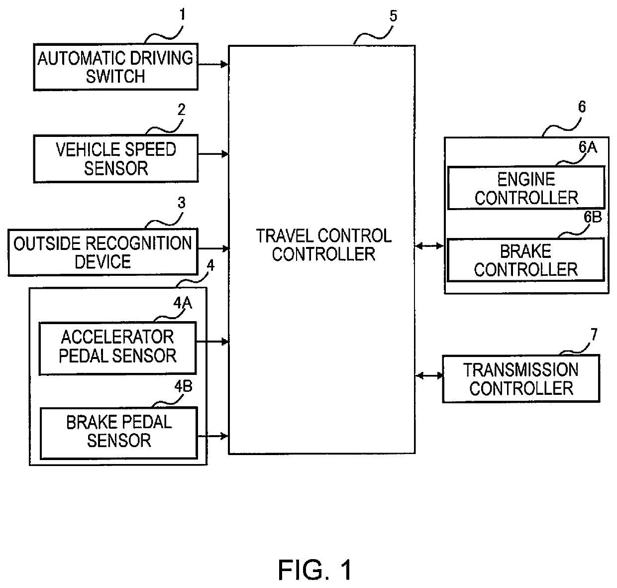
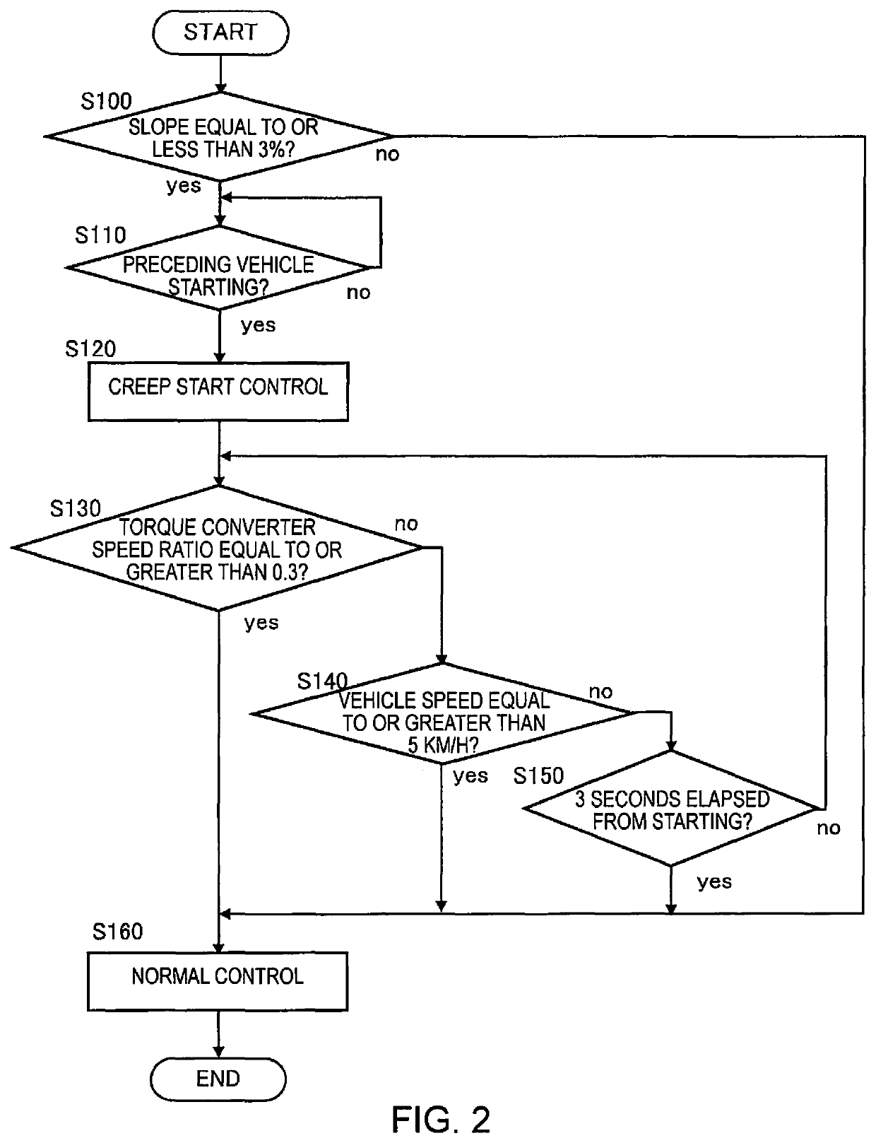
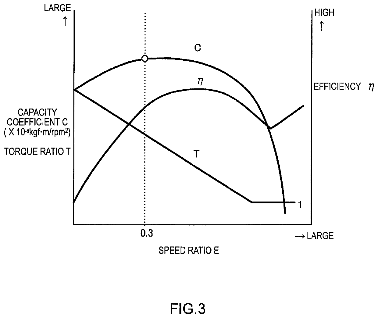
[0015]A first embodiment will be described with reference to FIGS. 1 to 4. FIG. 1 is a block diagram of a vehicle control system according to the first embodiment.

[0016]A vehicle according to the present embodiment is provided with an internal combustion engine (“engine” hereinbelow) as a drive source, and drive force generated by the engine is transmitted to a transmission via a torque converter.

[0017]An automatic driving switch 1 is a switch for instructing to set off and stop an automatic driving mode in which acceleration-deceleration rate control is performed automatically without an operation by a driver, or instructing to change a vehicle speed, acceleration, etc., during execution of the automatic driving mode. A state of the automatic driving switch 1 is outputted to a travel control controller 5 described hereinafter.

[0018]A vehicle speed sensor 2 is a sensor for detecting a vehicle speed of a host vehicle, and is constituted from a rotary encoder or other pulse generator ...

second embodiment

[0064]A second embodiment will be described with reference to FIGS. 5 and 6.

[0065]FIG. 5 is a block diagram of a vehicle control system according to the second embodiment. The control system in FIG. 5 is basically the same as in FIG. 1. However, the vehicle pertaining to the present embodiment is an electric vehicle having an electric motor as the drive source thereof, and an acceleration-deceleration rate control device 8 thereof is therefore provided with a motor controller 8A and a brake controller 8B.

[0066]In the second embodiment as well, the travel control controller 5 sets off from the creep torque and subsequently switches to normal control. However, the vehicle pertaining to the present embodiment does not have a torque converter, since the drive source thereof is an electric motor. Therefore, the present embodiment and the first embodiment differ with respect to the timing of switching to normal control after starting. The following description mainly relates to this diffe...


PUM


Abstract

A vehicle control method is provide for automatically controlling an acceleration-deceleration rate control of a vehicle including starting and stopping. The vehicle control method performs the starting of the vehicle at a starting time with a first drive force which exceeds a starting friction force, which is a friction force acting on the vehicle at the starting time. Then, the vehicle control method switches to a second drive force after performing the starting. The second drive force is greater than the first drive force. The second drive force is a drive force that is necessary to make a headway distance to a preceding vehicle equal to a pre-set headway distance when there is a preceding vehicle. The second drive force is a drive force that is necessary to accelerate to a pre-set vehicle speed when there is no the preceding vehicle.

Description

CROSS-REFERENCE TO RELATED APPLICATIONS[0001]This application is a U.S. national stage application of International Application No. PCT / JP2018 / 001763, filed on Jan. 22, 2018.TECHNICAL FIELD[0002]The present invention relates to a vehicle control for starting and stopping without an operation by a driver.BACKGROUND INFORMATION[0003]As an example of vehicle control for starting and stopping without an operation by a driver, JP 2002-234358 A discloses control whereby, when a preceding vehicle is present, the vehicle travels so as to follow the preceding vehicle while maintaining a pre-set headway distance, and when there is no preceding vehicle, the vehicle travels so as to maintain a pre-set vehicle speed. In the control disclosed in the document above, when starting so as to follow the preceding vehicle, or when starting from a state of having stopped in response to a stop signal or the like, a drive force is controlled so that the vehicle accelerates at an acceleration rate that cor...

Claims


Application Information

Patent Timeline
Patent Type & Authority Patents(United States)
IPC IPC(8): B60W10/06B60W10/10B60W30/16B60W30/14B60W40/076
CPCB60W30/16B60W10/06B60W10/10B60W30/143B60W40/076B60W2520/00B60W2552/15F02D29/02B60W2720/106B60W30/18027B60W30/18063B60W30/17
Inventor HIRANO, TOMOHISA
Owner NISSAN MOTOR CO LTD
Learn More