Eureka AIR delivers breakthrough ideas for toughest innovation challenges, trusted by R&D personnel around the world.

Multiple fuel system for internal combustion engines

a fuel system and internal combustion engine technology, applied in the direction of electrical control, process and machine control, instruments, etc., can solve the problems of engine damage and detrimental to overall performance at other speed/load conditions

Inactive Publication Date: 2011-11-08
TOYOTA JIDOSHA KK +1
View PDF8 Cites 40 Cited by
  • Summary
  • Abstract
  • Description
  • Claims
  • Application Information

AI Technical Summary

Benefits of technology

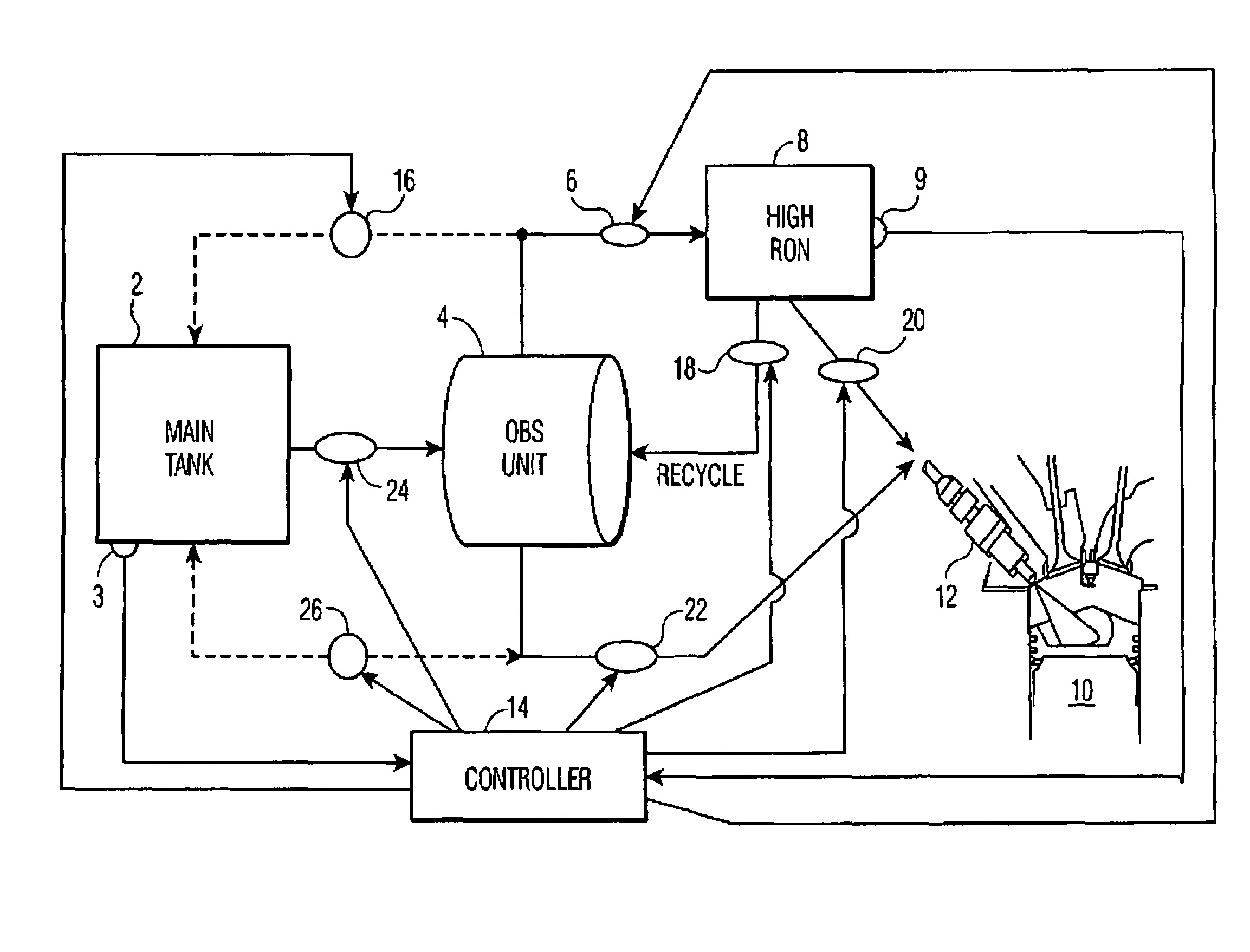
[0008]Another object of the present invention is to provide an improved multiple RON fuel supply system that includes an onboard separation (OBS) apparatus for separating intermediate research octane (IRON) fuel from a main tank into at least two grades, one a high research octane (HRON), and the other low research octane (LRON), whereby the production of these fuels by the OBS and their consumption are controlled for delivery to an associated internal combustion engine in response to the engine's operating conditions.
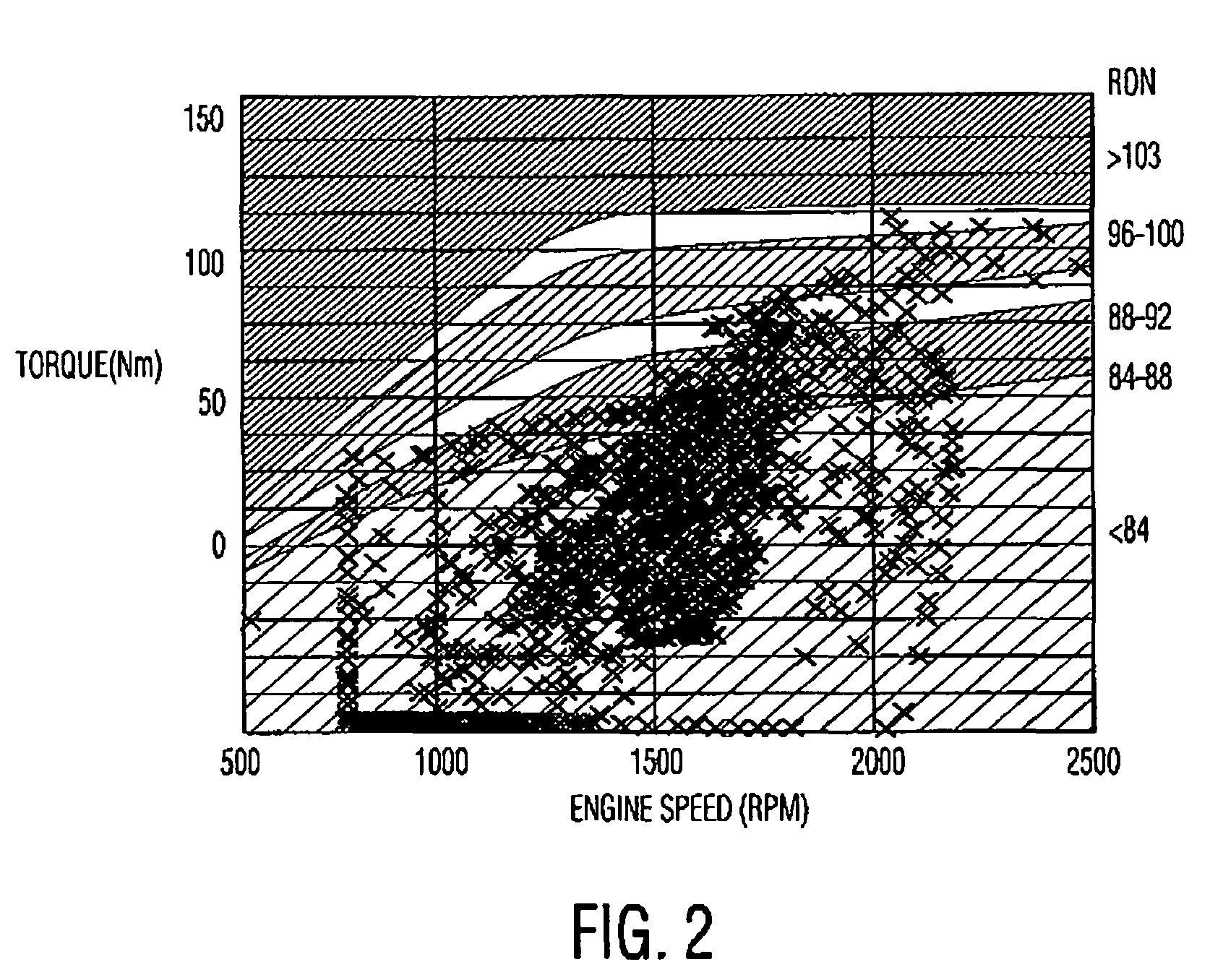
[0009]Another object of the invention is to provide a multiple fuel delivery system for driving an internal combustion engine, wherein the consumption of these fuels either individually or in various mixtures is controlled through use of an optimal RON map, the latter providing mapping of engine operating parameters such as torque, speed, gear ratio, accelerator, and velocity, and so forth, to the RON fuel required by the internal combustion engine over a range of engine drive cycle conditions. Also, the control is programmed to vary the production of the LRON and HRON from the OBS as a function of the fuel consumption by the engine at any given time.

Problems solved by technology

Both petroleum refineries and engine manufacturers are constantly faced with the challenge of continually improving their products to meet increasingly severe governmental efficiency and emission requirements, and consumers' desires for enhanced performance.
For example, engine manufacturers endeavor to inhibit to the maximum extent possible the phenomenon of auto-ignition which typically results in knocking, and can cause engine damage, when a fuel with insufficient knock-resistance is combusted in the engine.
This requires compromise, as often times fuel properties or engine parameters that are desirable under certain speed / load conditions prove detrimental to overall performance at other speed / load conditions.

Method used


Image

  • Multiple fuel system for internal combustion engines
  • Multiple fuel system for internal combustion engines
  • Multiple fuel system for internal combustion engines

Examples


Embodiment Construction

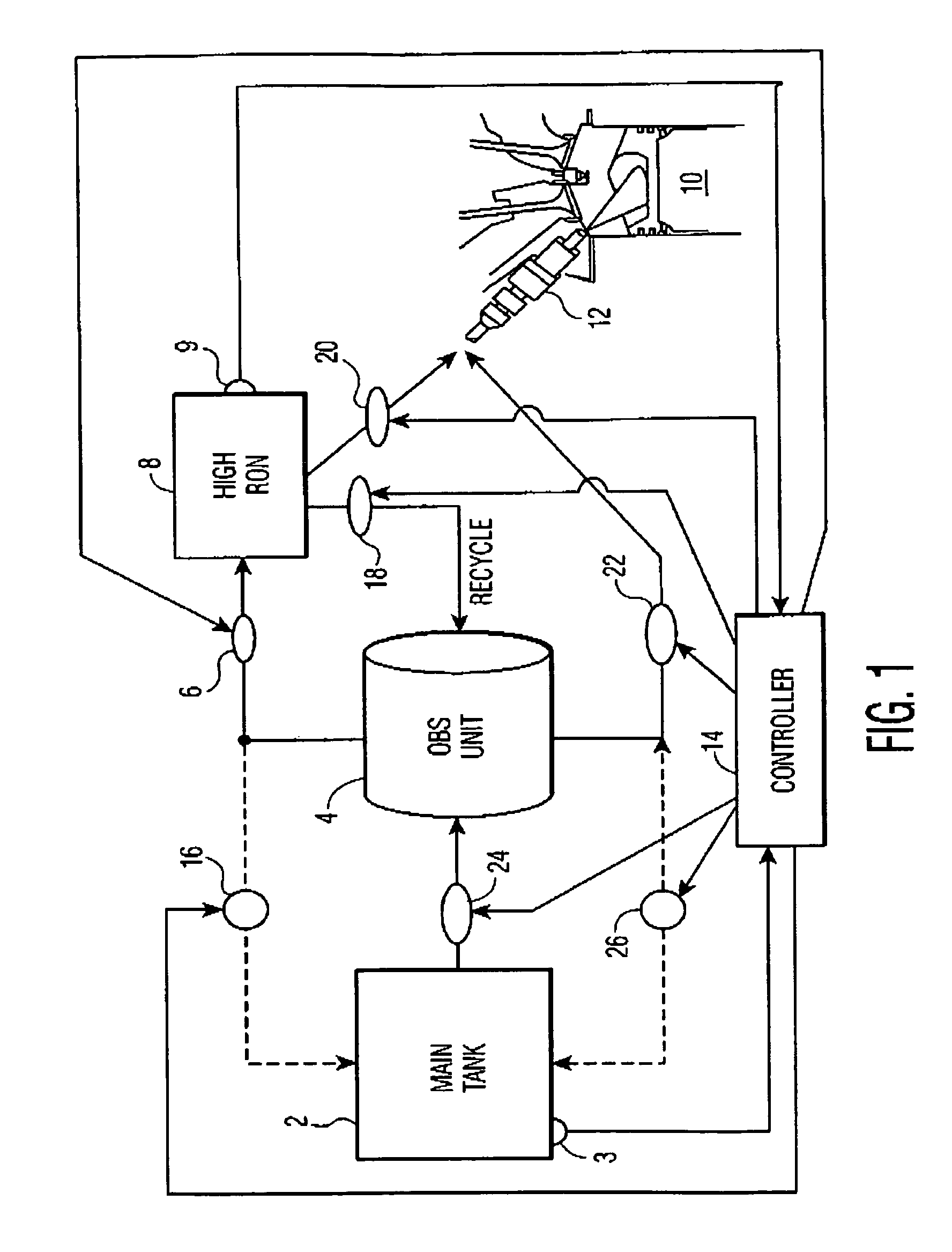
[0024]With reference to FIG. 1, a simplified block diagram of a fuel management system for one embodiment of the invention is shown. A main tank 2 for retaining an intermediate grade of Research Octane Number (RON) fuel is included in the associated vehicle. In this example, the intermediate RON fuel is also designated as IRON. A variable ratio pump 24 is operable for delivering the IRON fuel from the main tank 2 to an onboard separation (OBS) unit 4. The OBS unit 4 is operable for separating the IRON fuel into two grades, one being a high research octane (HRON) grade fuel, and the other being a low research octane (LRON) fuel. The HRON fuel is delivered from OBS unit 4 to an HRON fuel tank 8. The OBS unit 4 can be provided by separation devices using silica gel, distillation, membranes, and coated ceramic monoliths, for example. The preferred embodiments for an OBS unit 4 will be discussed in greater detail below. In the following discussion, for purposes of example, OBS unit 4 use...


PUM


Abstract

A fuel management system mounted on a vehicle is operative to feed individually or a mixture of grades of relatively low, intermediate, and high autoignition temperature fuels to an associated internal combustion engine. The system includes an on board separation unit (OBS unit) for receiving and separating intermediate autoignition temperature (IAT) fuel into low and high autoignition temperature fuels, LAT and HAT, respectively. The production rate of the LAT and HAT fuels by the OBS unit is controlled to substantially match the consumption requirements of the engine at any given time for the LAT and HAT fuels.

Description

[0001]This application claims the benefit of U.S. Provisional Application No. 61 / 009,266 filed Dec. 27, 2007.RELATED APPLICATIONS[0002]The present invention is related to U.S. Provisional Application No. 61 / 009,336, entitled “Fuel Management For Vehicles Equipped With Multiple Tanks for Different Grades Of Fuel,” filed on the same day herewith, having common inventorship herewith, and common ownership; to Ser. No. 11 / 187,672, filed on Jul. 22, 2005, for “Heat Pipe For Self Limiting Heating Of Gasoline For Onboard Octane Segregation”; and to Provisional Application No. 60 / 785,426, filed on Mar. 24, 2006, for “Heat Pipe With Controlled Fluid Charge.” The teachings of the related Applications are incorporated by reference herein to the extent that they do not conflict herewith.FIELD OF THE INVENTION[0003]The present invention relates generally to systems for using multiple fuel of differing grades, such as different research octane numbers (RON) for spark ignition engines, and differen...

Claims


Application Information

Patent Timeline
Patent Type & Authority Patents(United States)
IPC IPC(8): F02M43/04F02M43/00
CPCF02D41/0025F02M37/0088F02M37/0064Y02T10/36Y02T10/30Y10T137/2509Y10T137/27
Inventor SENGUPTA, BHASKARKUMARAN, KRISHNANWEISSMAN, WALTERPARTRIDGE, RANDALL D.SUGIYAMA, KOUSEKIYOEDA, KEIJIODA, TOMIHISAIWASHITA, YOSHIHIRO
Owner TOYOTA JIDOSHA KK
Why Eureka
Eureka Blog
Learn More