

Structure for introducing gas into intake air
a technology for internal combustion engines and structures, applied in combustion-air/fuel-air treatment, machines/engines, mechanical equipment, etc., can solve the problems of not being able to enhance the fuel efficiency to a sufficient degree, the internal combustion engine that includes a plurality of banks without any modification, and not being able to apply the technology described
- Summary
- Abstract
- Description
- Claims
- Application Information
AI Technical Summary
Benefits of technology
Problems solved by technology
Method used
Image

Examples
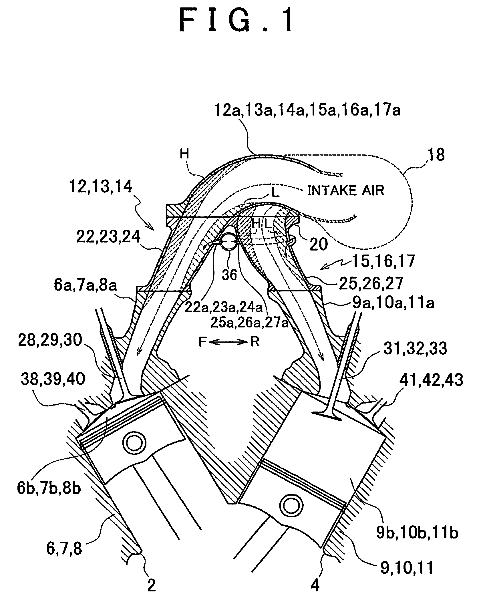
first embodiment
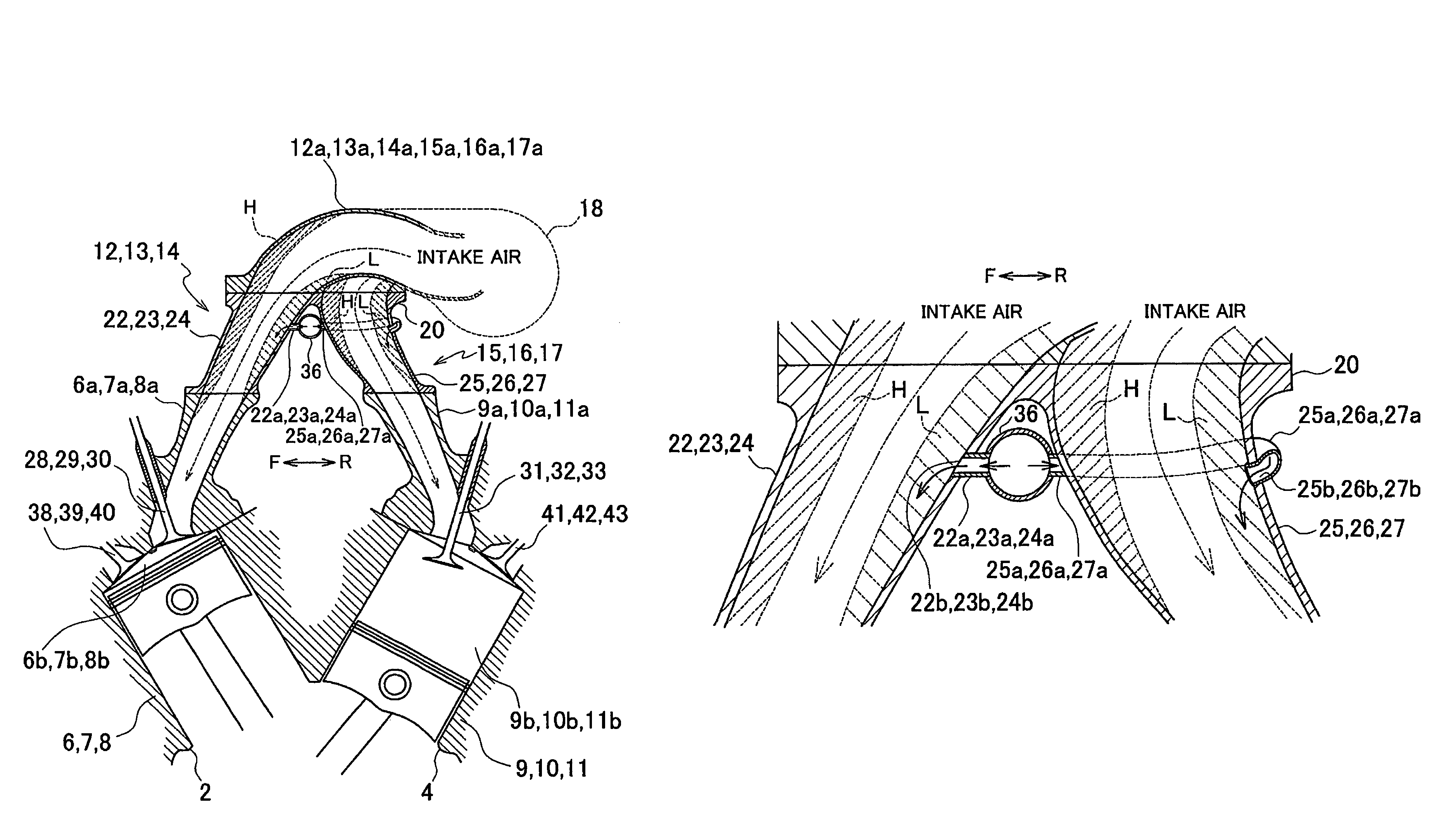
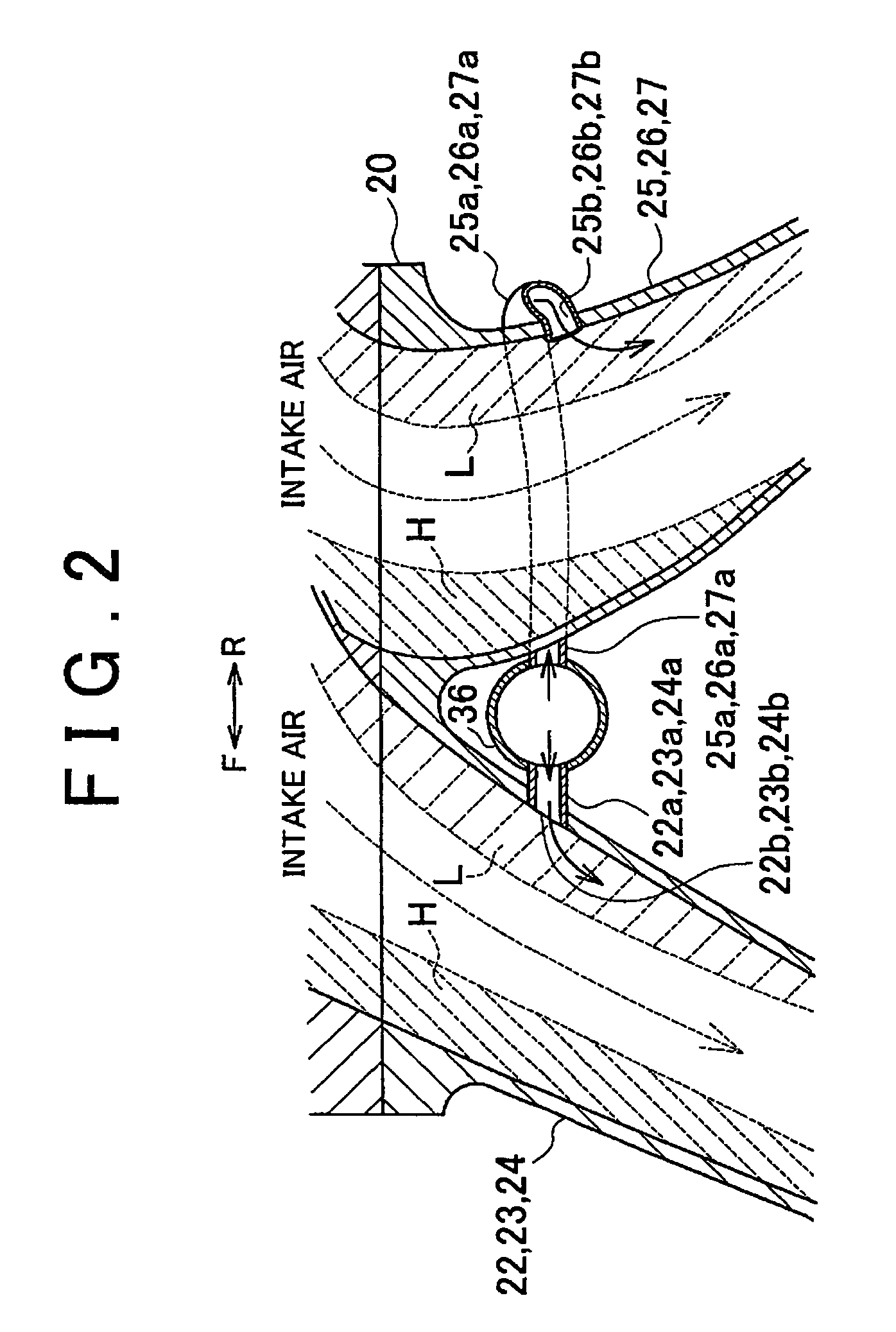
[0046]According to the invention described above, the following effects are obtained. 1) The inlets 22b to 24b through which the exhaust gas is introduced from the EGR pipe 36 into the intake passages 12 to 14 for the cylinders 6 to 8 in the right bank 2, respectively, are within the low-pressure regions L. Similarly, the inlets 25b to 27b through which the exhaust gas is introduced from the EGR pipe 36 into the intake passages 15 to 17 for the cylinders 9 to 11 in the left bank 4, respectively, are within the low-pressure regions L. That is, the exhaust gas inlets 22b to 27b are formed at positions where the pressure of the intake air flowing through the branch pipes 22 to 24 for the cylinders 6 to 8 in the right bank 2, respectively, and the pressure of the intake air flowing through the branch pipes 25 to 27 for the cylinders 9 to 11 in the left bank 4, respectively, are both low and therefore substantially equal to each other. Accordingly, the amount of exhaust gas that is intro...
second embodiment
[0052]According to the invention described above, the following effect is obtained. 1) The inlets 72b to 74b through which the exhaust gas is introduced from the EGR pipe 86 into the intake passages 62 to 64 for cylinders 56 to 58 in the right bank 52, respectively, are within the high-pressure regions H. Similarly, the inlets 75b to 77b through which the exhaust gas is introduced from the EGR pipe 86 into the intake passages 65 to 67 for cylinders 59 to 61 in the left bank 54, respectively, are within the high-pressure regions H. That is, the exhaust gas inlets 72b to 77b are formed at positions where the pressure of the intake air flowing through the branch pipes 72 to 74 for the cylinders 56 to 58 in the right bank 52 and the pressure of the intake air flowing through the branch pipes 75 to 77 for the cylinders 59 to 61 in the left bank 54 are substantially equal to each other. Accordingly, the amount of exhaust gas that is introduced into each of the cylinders 56 to 58 in the ri...
PUM
 Abstract
Description
Claims
Application Information