Electrical connector with stable retaining terminals

a technology of electrical connectors and terminals, applied in the direction of fixed connections, coupling device connections, coupling device details, etc., can solve the problems of limited elasticity, unreliable soldering, and large strength, and achieve the effects of improving elasticity, facilitating insertion of solder balls, and improving soldering reliability

Inactive Publication Date: 2011-11-08
LOTES
View PDF2 Cites 25 Cited by
  • Summary
  • Abstract
  • Description
  • Claims
  • Application Information

AI Technical Summary

Benefits of technology

[0010]Compared with the prior art, among other things, the electrical connector of the present invention is configured such that a groove is formed on the first retaining portion, the lengths of the arms of the retaining forces of the second retaining portion and the third retaining portion to retain the sol

Problems solved by technology

However, the terminal 2 has some defects in the structure thereof which result in several problems mainly as follows.
However, limited lengths of the second retaining portion 23 and the third retaining portion 24 result in undesirable lengths of the arms of the retaining forces of the second retaining portion 23 and the third retaining portion 24 to retain the solder ball 3, thus causing great strength and limited elasticity of the second retaining portion 23 and the third retaining portion 24, so that at the time of inserting the solder

Method used


Image

  • Electrical connector with stable retaining terminals
  • Electrical connector with stable retaining terminals
  • Electrical connector with stable retaining terminals

Examples


Embodiment Construction

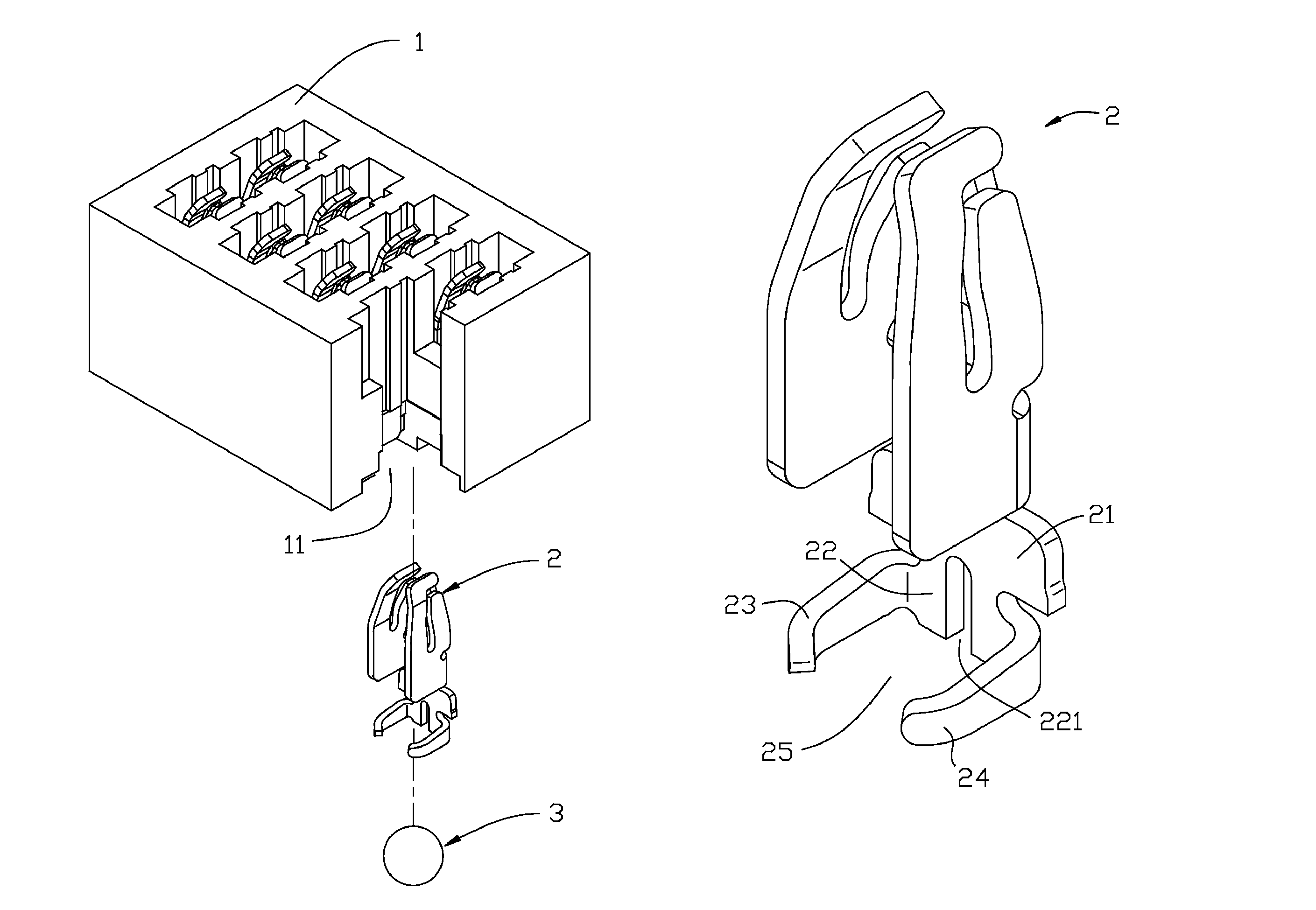
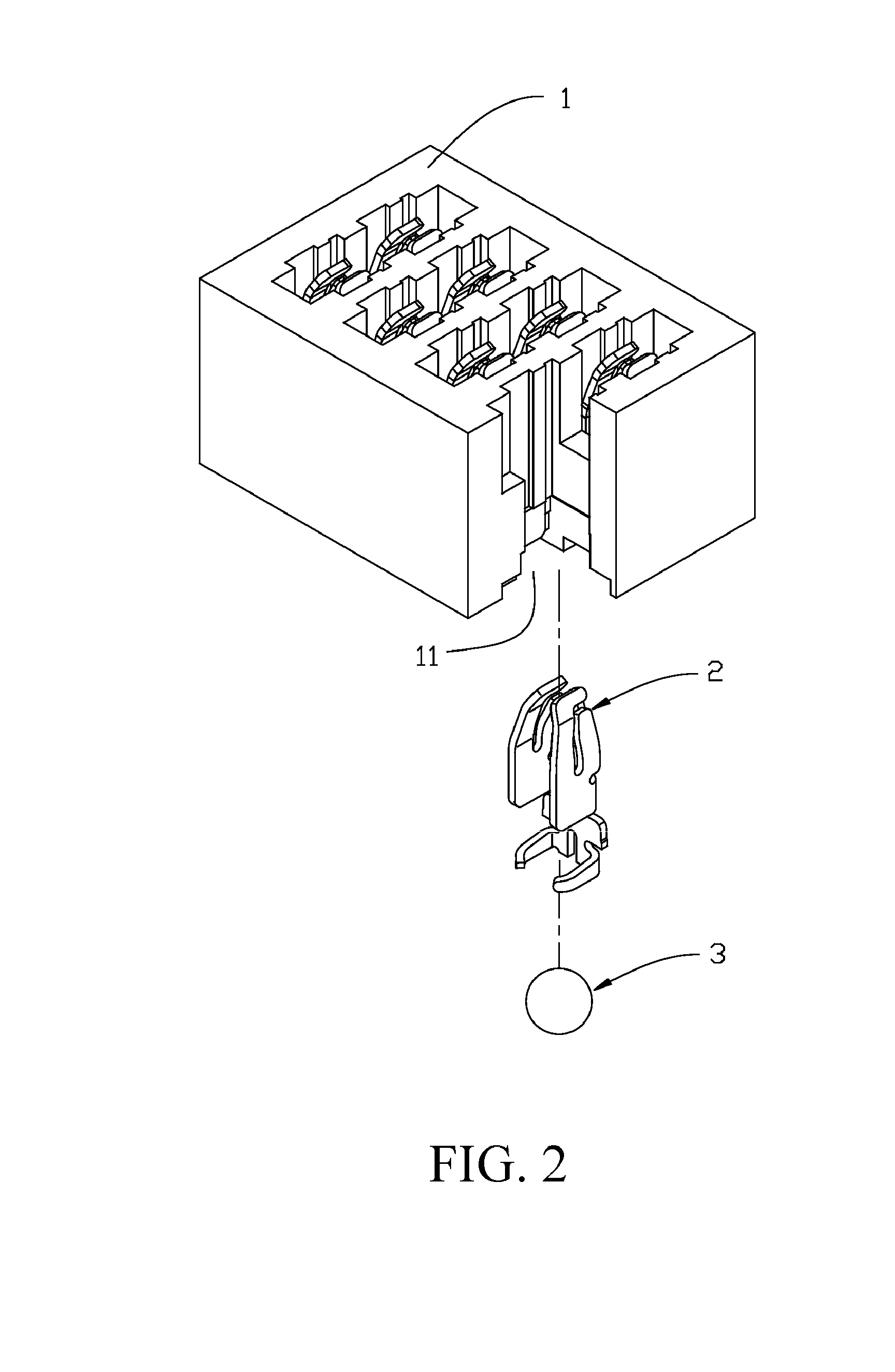
[0019]The present invention is more particularly described in the following examples that are intended as illustrative only since numerous modifications and variations therein will be apparent to those skilled in the art. Various embodiments of the invention are now described in detail. Referring to the drawings, FIGS. 2-6, like numbers indicate like components throughout the views. As used in the description herein and throughout the claims that follow, the meaning of “a”, “an”, and “the” includes plural reference unless the context clearly dictates otherwise. Also, as used in the description herein and throughout the claims that follow, the meaning of “in” includes “in” and “on” unless the context clearly dictates otherwise.

[0020]The terms used in this specification generally have their ordinary meanings in the art, within the context of the invention, and in the specific context where each term is used. Certain terms that are used to describe the invention are discussed below, or...


PUM


Abstract

An electrical connector includes an insulating body, having a plurality of receiving slots running through the insulating body; a plurality of terminals respectively received in the receiving slots; and a plurality of solder balls, in which each of the solder balls is disposed corresponding to each terminal and each receiving slot. Each terminal includes a base, a first retaining portion formed by extending downwards the base, a second retaining portion and a third retaining portion formed by bending and extending two side surfaces of the first retaining portion, and a groove formed at one end of the first retaining portion away from the base.

Description

CROSS-REFERENCE TO RELATED PATENT APPLICATION[0001]This non-provisional application claims benefits and priority under 35 U.S.C. §119(a) on Chinese Patent Application No. 201020579427.9 filed in The People's Republic of China on Oct. 22, 2010, which is incorporated herein by reference in its entirety.FIELD OF THE INVENTION[0002]The present invention relates to an electrical connector, and more particularly to an electrical connector for electrically connecting a chip module to a circuit board.BACKGROUND OF THE INVENTION[0003]FIG. 1 shows an electrical connector currently widely used in the field for electrically connecting a chip module to a circuit board. The electrical connector includes an insulating body 1, where a plurality of receiving slots 11 runs through the insulating body 1, a plurality of terminals 2, in which each of the terminals 2 is correspondingly disposed in one of the receiving slots 11, and a plurality of solder balls 3, respectively disposed in one of the receiv...

Claims


Application Information

Patent Timeline
IPC IPC(8): H01R12/00
CPCH01R12/57
Inventor JU, TED
Owner LOTES
Why Eureka
Try Eureka