Ulnar head prosthesis system

a prosthesis and ulnar head technology, applied in the field of ulnar head prosthesis system, can solve the problems of distal radioulnar disorder, pain, weakness, instability and loss of forearm rotation, and pain of forearm rotation loss, and achieve the effect of preventing relative rotation

Inactive Publication Date: 2011-11-08
REMI SCI
View PDF172 Cites 45 Cited by
  • Summary
  • Abstract
  • Description
  • Claims
  • Application Information

AI Technical Summary

Benefits of technology

[0007]In at least one embodiment, the present invention provides an ulnar prosthesis assembly comprising a head formed with a curved surface extending between opposed ends and a stem. One of the ends of the head has an attachment bore defined therein. The attachment bore generally defines a bore end surface. The stem has a stem body extending between a proximal end configured for implantation in a target bone and a distal end configured to be received in the attachment bore. The distal end has a distal end surface with at least one projection extending therefrom and configured such that when the distal end is received in the attachment bore, the at least one projection penetrates the bore end surface and prevents relative rotation between the head and the stem.

Problems solved by technology

Disorders of the distal radio-ulnar joint are common and usually associated with pain, weakness, instability and loss of forearm rotation.
Any loss of congruity between the sigmoid fossa of the radius and the ulnar head will result in painful loss of forearm rotation.
Furthermore, trauma may result in acute dislocation of the distal radio-ulnar joint itself, often in association with radial head fracture and tear of the interosseous membrane.
Finally, many patients suffer from painful instability following previous surgical procedures on the distal radio-ulnar joint.
The current salvage procedures without a prosthetic implant include, Darrach resection, hemi-resection, and suave-kapandji; however, all the surgical techniques render the distal ulna unstable leading to recurrence of pain, instability, and weakness.
Although any of the above procedures may produce reasonable results if correctly carried out and in appropriate patients, there are, however, many patients who are discontented with the results of surgery and who are seeking a suitable revision procedure to restore stability and pain free rotation at the distal radio-ulnar joint.

Method used


Image

  • Ulnar head prosthesis system
  • Ulnar head prosthesis system
  • Ulnar head prosthesis system

Examples


Embodiment Construction

[0037]Although the invention is illustrated and described herein with reference to specific embodiments, the invention is not intended to be limited to the details shown. Rather, various modifications may be made in the details within the scope and range of equivalents of the claims and without departing from the invention.

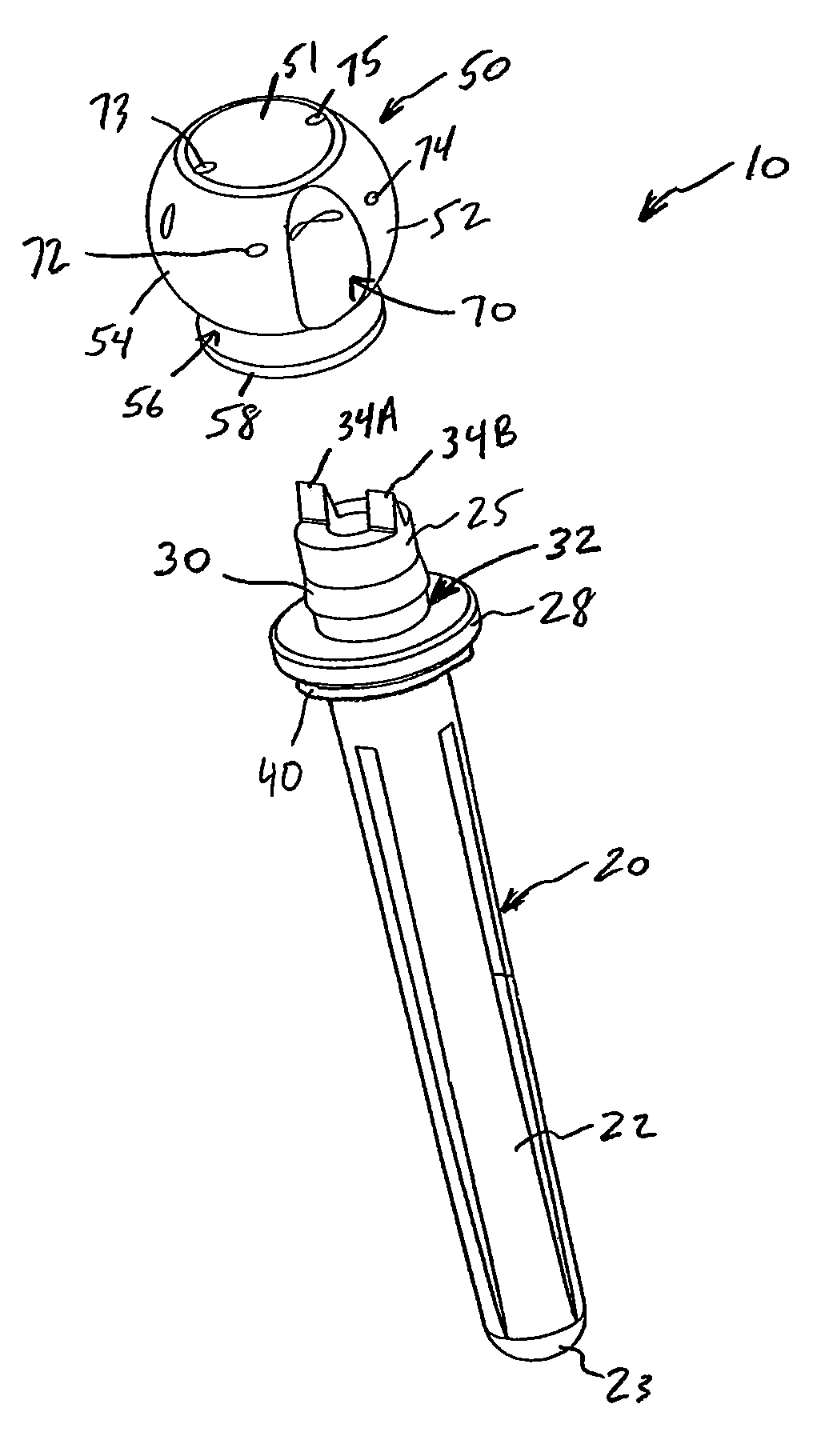
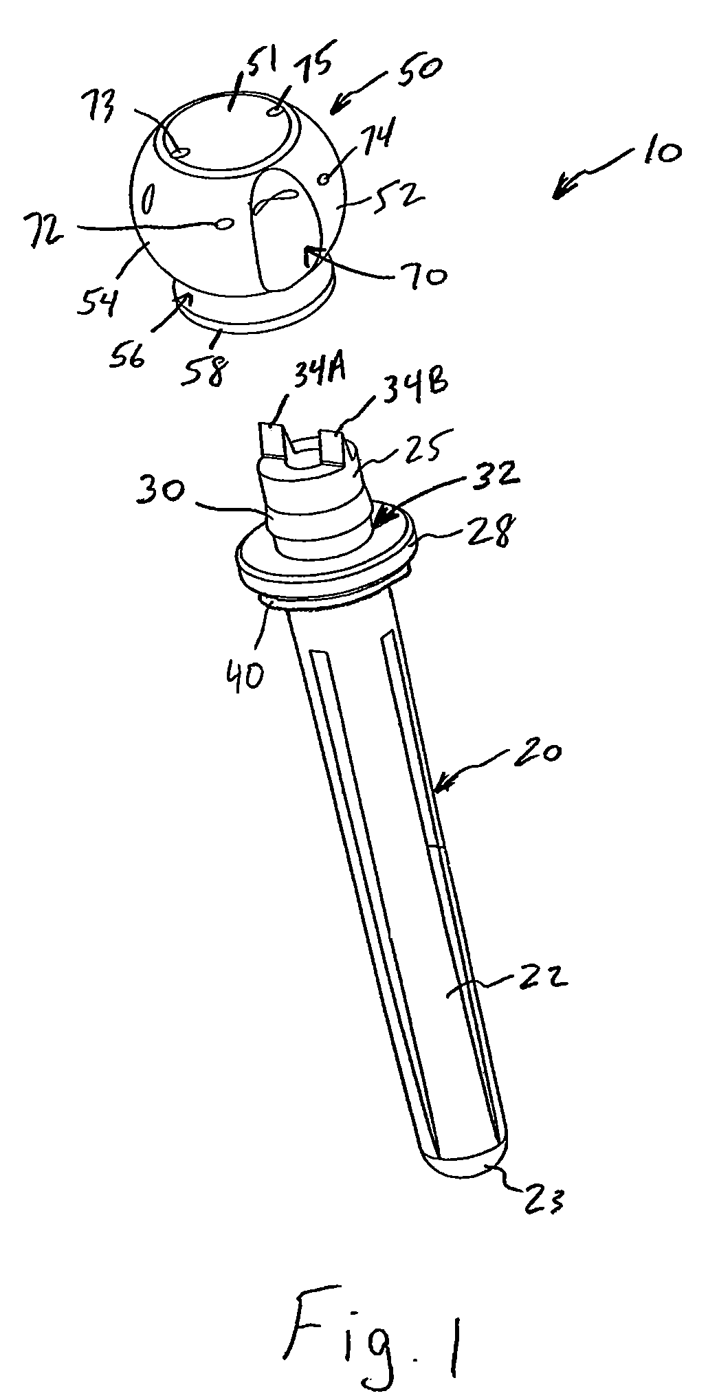
[0038]Referring to FIGS. 1-8, a prosthesis assembly 10 in accordance with an embodiment of the present invention will be described. The prosthesis assembly 10 is a modular assembly generally comprising a stem 20 and a head 50. The stem 20 is configured to be implanted in the intermedullary canal of an ulnar bone. In the present embodiment, the prosthesis assembly 10 is configured to provide for a total ulnar head replacement, however, the present invention may also be used for partial or hemi ulnar head replacement as described below.

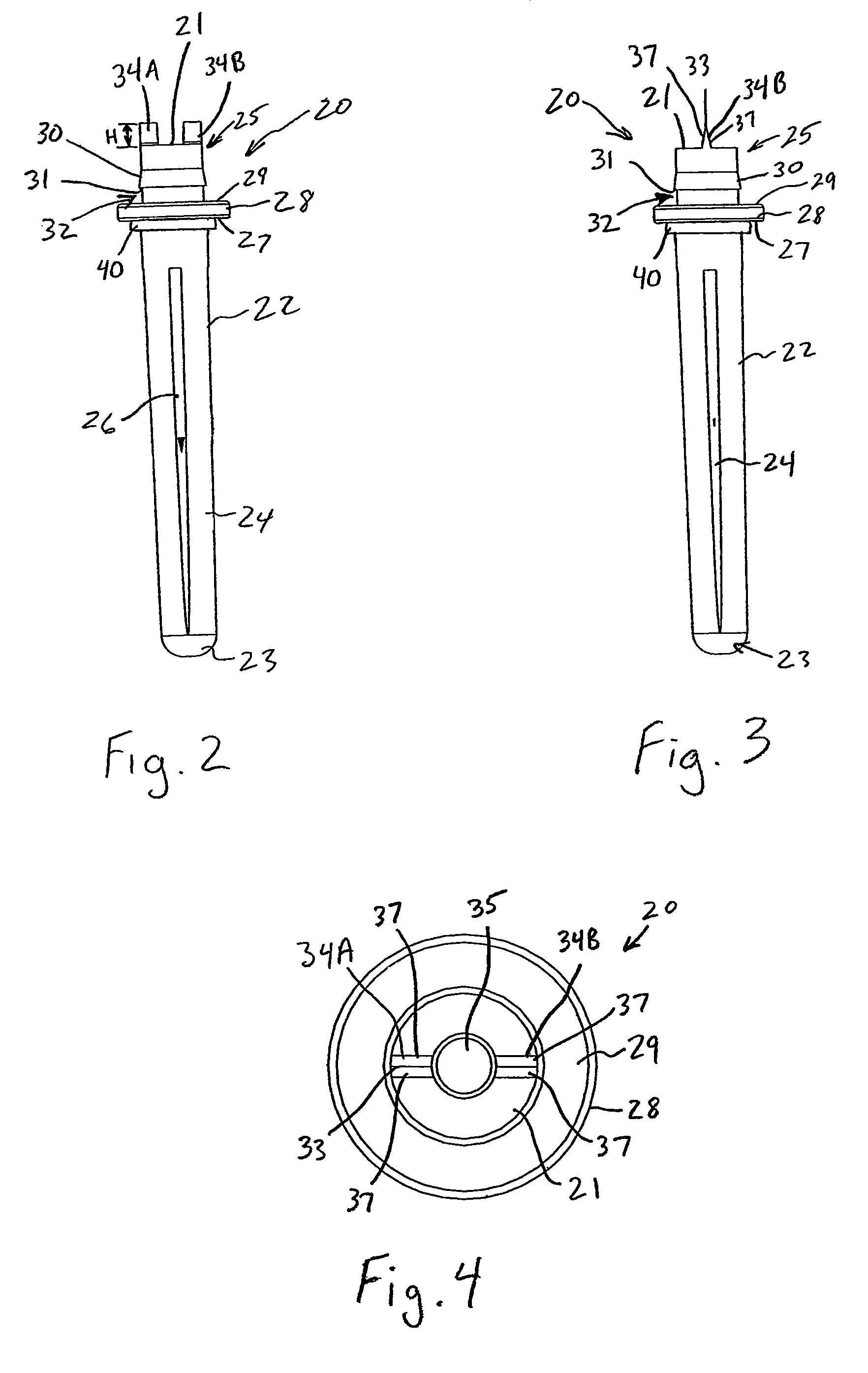
[0039]Referring to FIGS. 2-4, the stem 20 has an elongate body 22 extending between a proximal end 23 and a distal end 25. The stem ...


PUM


Abstract

An ulnar prosthesis assembly comprising a head formed with a curved surface extending between opposed ends and a stem. One of the ends of the head has an attachment bore defined therein. The attachment bore generally has a first diameter and includes an attachment groove thereabout with a second diameter greater than the first diameter to define at least one attachment shoulder. The stem has a stem body extending between a proximal end configured for implantation in a target bone and a distal end configured to be received in the attachment bore. The distal end has a locking flange extending radially therefrom. The locking flange defines a locking shoulder having a diameter greater than the first diameter such that upon receipt in the attachment bore, the locking shoulder engages the attachment shoulder.

Description

BACKGROUND OF THE INVENTION[0001]The present invention relates generally to a prosthesis for the distal radio-ulnar joint and more particularly to a prosthesis for the restoration of pain free rotation of the forearm and stability of the ulna and wrist.[0002]The ulnar head is an integral portion of the distal radio-ulnar joint (DRUJ). The DRUJ is essential for stable forearm rotation and the ulnar head serves as the fixed fulcrum at which the radius sigmoid notch articulates. The radius of curvature of the sigmoid notch is approximately twice that of the ulnar head and the motion between the two surfaces can be accurately described as rolling and sliding.[0003]Disorders of the distal radio-ulnar joint are common and usually associated with pain, weakness, instability and loss of forearm rotation. Any loss of congruity between the sigmoid fossa of the radius and the ulnar head will result in painful loss of forearm rotation. Causes include congenital abnormalities such as Madelung's ...

Claims


Application Information

Patent Timeline
Patent Type & Authority Patents(United States)
IPC IPC(8): A61F2/42
CPCA61F2/3804A61F2/4605A61F2/4637A61F2/30965A61F2002/30065A61F2002/30331A61F2002/30332A61F2002/30433A61F2002/30474A61F2002/30485A61F2002/305A61F2002/30528A61F2002/3054A61F2002/30574A61F2002/3069A61F2002/30878A61F2002/3093A61F2002/3831A61F2002/4619A61F2002/4622A61F2002/4623A61F2002/4627A61F2002/4629A61F2002/4641A61F2210/0071A61F2220/0025A61F2220/0033A61F2220/0041A61F2/4603
Inventor NAIDU, SANJIV
Owner REMI SCI
Why Eureka
Try Eureka