Solar energy collection devices

a solar energy and collection device technology, applied in the safety of solar heat collectors, pv power plants, light and heating equipment, etc., can solve the problems of 7% efficiency loss due to reflection, limited supply of photovoltaic materials, etc., to improve the versatility and simplicity of solar collection devices, reduce costs, and improve solar energy collection

Inactive Publication Date: 2011-11-08
KHAZENI KASRA +1
View PDF25 Cites 16 Cited by
  • Summary
  • Abstract
  • Description
  • Claims
  • Application Information

AI Technical Summary

Benefits of technology

[0013]The invention is directed to devices, methods, systems and apparatus for improving solar energy collection, reducing costs associated with manufacture of solar energy collection and improving the versatility and simplicity of solar collection devices. The methods and apparatus disclosed herein may provide a number of solutions to the high demand, but limited supply for photovoltaic (“PV”) material, especially high-efficiency PV material for converting solar energy to electrical energy.
[0014]According to one aspect of the invention, a collection device includes a series of glass (or other transparent material) rods, e.g., rods with a circular cross section, that are arranged parallel and side by side to each other. Each rod acts as a linear lens having, e.g., approximately a 5 to 1 concentration ratio when standard glass is used and the PV material is attached directly to the rod lenses. The rods can have a larger or smaller concentration ratio depending on the index of refraction of the material. Tracking may or may not be used. In some embodiments, tracking may not be necessary. Instead, the collection device may be rotated about a single axis normal to the panel, thereby rotating all rods simultaneously to allow collection of solar energy. In some embodiments, a minimal movement may be achieved by rotation of each rod lens about its longitudinal axis within the panel, thereby allowing the collection of solar energy as the sun's apparent position changes. Other aspects of the disclosure which can be practiced in view of the disclosure: no requirement for active cooling of the PV cells and no requirement for installation at an angle or orientation, thereby allowing a solar collection device to be more easily deployed; the same footprint as conventional panels; a higher efficiency than a flat panel (assuming the same type of PV material is used). In some embodiments, a solar collection device may be self installed, which offers the advantage of dramatically decreasing the installation cost (up to about 50%), as will be apparent from the disclosure. In other embodiments, a panel containing the rod lenses can be tracked on a 1D tracking platform without the need for each individual rod lens to rotate. In other embodiments, the cross section of the rod lenses can be elliptical or any other shape.
[0015]According to one aspect of the disclosure, rod lenses are used to collect solar energy onto a strip of PV material. According to these embodiments, the PV material may be affixed to the rod lenses and the rod lenses rotated about their longitudinal axis (or the panel axis) to follow the sun. When the PV material is affixed to the rods, the PV material may be made separately, then affixed to the rods using, e.g., an index-matching adhesive, or formed on the rods, e.g., by chemical vapor deposition, evaporation, electroplating, or other suitable manufacturing techniques. In terms of assessing the efficiency of a collector using rod lenses according to the disclosure, it is estimated that about 7% efficiency is lost due to reflection. However, as compared to a flat panel, rod lenses made of standard glass may have an approximate 5 to 1 concentration ratio, which provides about a 10% gain in efficiency over a flat panel using the same PV material. The combined effect, i.e., loss due to reflection (due to the curved lens surface)+5 to 1 concentration ratio, means a solar collector according to the disclosure is able to achieve the same, or in some cases a higher level of efficiency but with a lower manufacturing cost and in some cases installation cost. A rod lens may have a simple shape, e.g., cylindrical, which provides costs advantages because this structure is readily available at high volumes from most glass manufacturers. A circular cross-section rod lens may be desirable when collecting solar energy by rotating each rod because the lens is rotationally symmetric. Thus, when collecting solar energy by rotating lenses about their longitudinal axes, the individual lenses can be packed together closely without interface from neighboring rods.
[0044]According to another embodiment, there is a method for increasing the acceptance angle for a solar panel, the solar panel including a plurality of concentrators and corresponding PV material configured to receive focused light from the concentrators. These methods include the step of rotating each of the concentrators about their lens axes as the sun's apparent position in the sky changes.

Problems solved by technology

The methods and apparatus disclosed herein may provide a number of solutions to the high demand, but limited supply for photovoltaic (“PV”) material, especially high-efficiency PV material for converting solar energy to electrical energy.
In terms of assessing the efficiency of a collector using rod lenses according to the disclosure, it is estimated that about 7% efficiency is lost due to reflection.

Method used


Image

  • Solar energy collection devices
  • Solar energy collection devices
  • Solar energy collection devices

Examples


Embodiment Construction

-21B show portions of the solar collecting element of FIG. 20 according to embodiments with and without additional concentrators, e.g., reflecting elements, positioned adjacent a metal grid for conducting current. The concentrators may be incorporated into the solar collecting element in accordance with one or more of the embodiments discussed in connection with FIGS. 3-4.

[0068]FIG. 21C depicts another embodiment of a solar collecting element including a circular rod lens with attached PV strip. According to these embodiments, a groove may be formed in the lens. The metal grid and concentrators may then be attached within the groove, e.g., with a suitable adhesive.

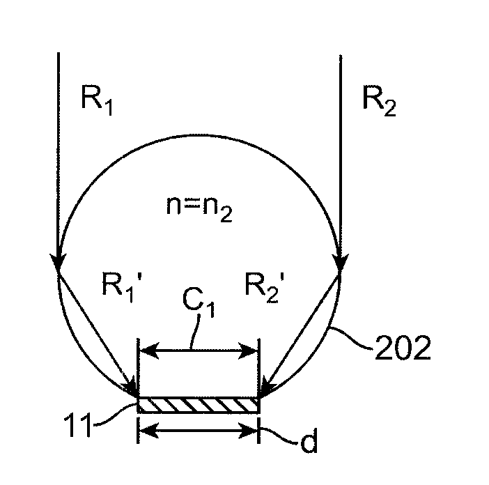
[0069]FIGS. 22A-22D show ray traces for various embodiments of a solar collection device.

[0070]FIG. 23 depicts an example of a static solar collection device constructed in accordance with the principles discussed in connection with FIGS. 9A-9B.

[0071]FIG. 24A depicts one embodiment of a linear concentrator having unused (n...


PUM


Abstract

Devices and methods for collecting solar energy using photovoltaic material are disclosed.

Description

PRIORITY STATEMENT[0001]This application claims the benefit of U.S. Provisional Application No. 61 / 052,117 filed May 9, 2008 and U.S. Provisional Application No. 61 / 088,967 filed Aug. 14, 2008.BACKGROUND OF THE INVENTION[0002]1. Field of the Invention[0003]This invention relates to devices and methods for the collection of solar energy using a photovoltaic solar cell.[0004]2. Back ground and Description of the State of the Art[0005]FIGS. 1A-1B illustrates a conventional construction for photovoltaic (PV) cells, e.g., a solar cell, which converts light energy to electricity. In this example, the cell 1 is generally square-like with an upper surface 2 corresponding to a sun-receiving or sun-facing side 2 of the solar cell 1. The opposing surface 3 faces away from the direction of sunlight. In this example, the solar cell 1 has an n-type doped silicon layer and p-type doped silicon layer separated by a junction layer. The sun-facing side 2 has a surface area made up of the PV material,...

Claims


Application Information

Patent Timeline
Patent Type & Authority Patents(United States)
IPC IPC(8): H01L31/0232F24S23/30
CPCF24J2/08F24J2/461F24J2/541H01L31/0547H02S20/00H01L31/0543Y02E10/52Y02E10/47F24S23/30F24S30/425F24S40/20F24S50/20H02S20/30H02S20/32
Inventor KHAZENI, KASRAAALAEI, FARAJGHAFOURI, SAEIDFARNAAM, KAMBIZ
Owner KHAZENI KASRA
Why Eureka
Try Eureka