
Vectorisation of colour gradients

a colour gradient and vectorisation technology, applied in the field of computer graphics, can solve the problems of consuming a non-trivial amount of memory, difficult to edit the resultant colour data using simple controls, and computationally expensive rendering of all the areas of flat colour

Inactive Publication Date: 2011-11-08
CANON KK
View PDF10 Cites 10 Cited by
  • Summary
  • Abstract
  • Description
  • Claims
  • Application Information

AI Technical Summary

Problems solved by technology

In the second case in which small areas are converted to flat filled objects, the main problem is that rendering all the areas of flat colour is computationally expensive.
In both of the described cases, the resultant colour data may be difficult to edit using simple controls (for example, changing the start and / or end points for a linear gradient).
In addition, the colour data consumes a non-trivial amount of memory.

Method used


Image

  • Vectorisation of colour gradients
  • Vectorisation of colour gradients
  • Vectorisation of colour gradients

Examples


Embodiment Construction

ll now be described with reference to the following drawings, in which:

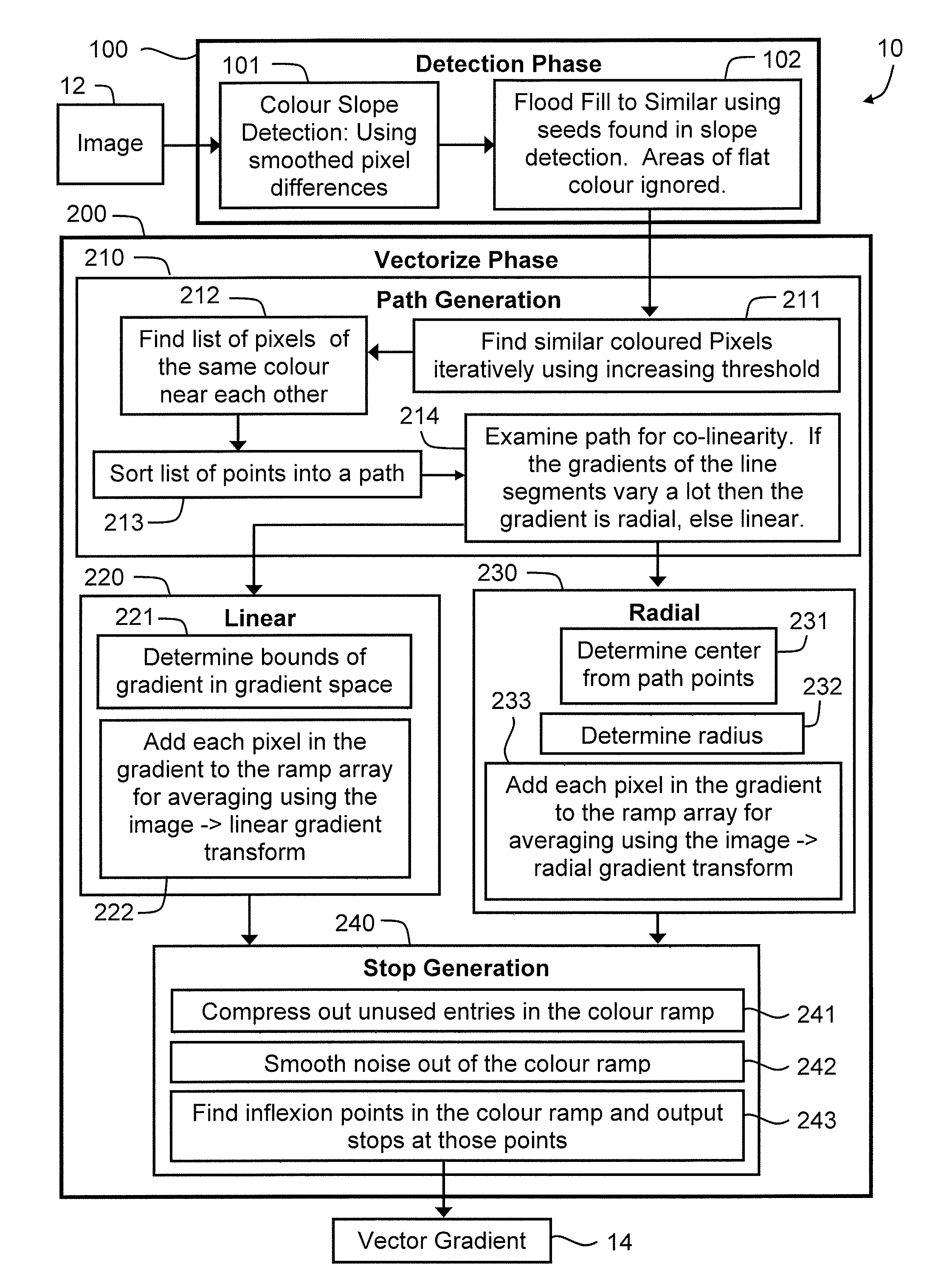
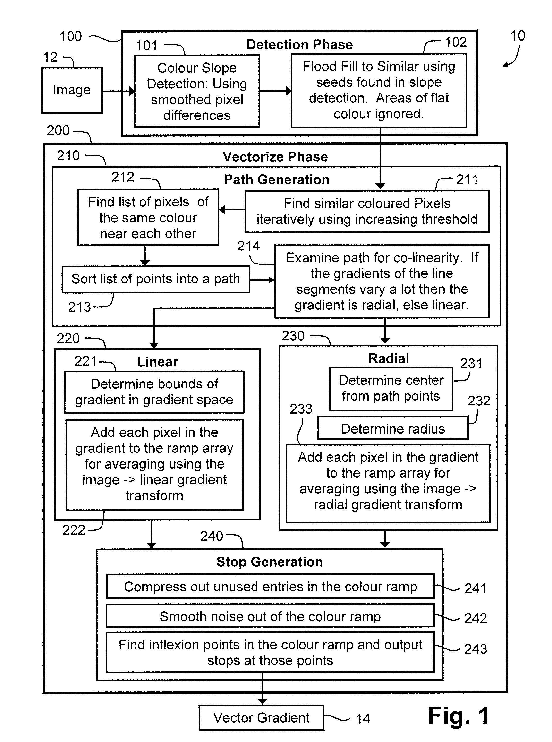
[0036]FIG. 1 is a flow chart of a method of generating a vector description of one or more colour gradients in an image;

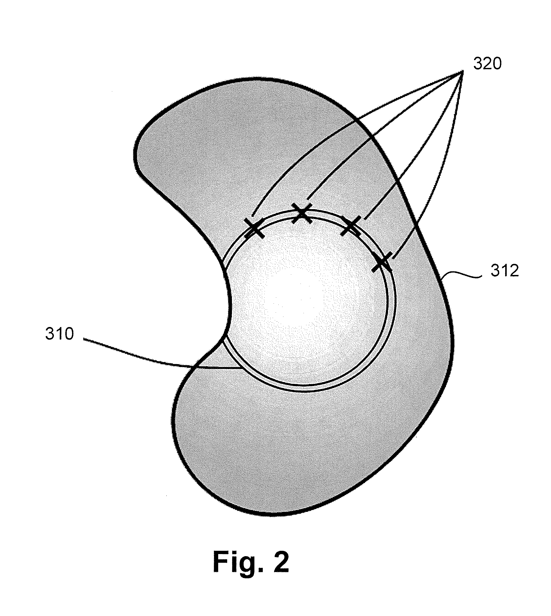
[0037]FIG. 2 shows an object used to illustrate the path generation step of the method of FIG. 1;

[0038]FIG. 3 shows an object used to illustrate a prior art method for approximating a raster bitmap fill;

[0039]FIG. 4 shows an object used to illustrate finding the parameters of a linear gradient according to the method of FIG. 1;

[0040]FIG. 5 shows an object used to illustrate finding the parameters of a radial gradient according to the method of FIG. 1;

[0041]FIG. 6 is a schematic block diagram of a system in which the method of FIG. 1 may be applied; and

[0042]FIG. 7 is a schematic block diagram of a general-purpose computer on which the described methods may be practiced.

DETAILED DESCRIPTION INCLUDING BEST MODE

[0043]There are many circumstances in which it may be desired to convert a raster bitmap...


PUM


Abstract

A method is described of generating a vector description of a color gradient in an image. The image comprises an array of pixels, each pixel having one or more associated color values. The image has at least one gradient area in which at least one of the color values varies between neighboring pixels. In each gradient area, a path is generated (step 210) comprising pixels having substantially the same color. Linear paths (403) and circular paths (501) are described. One or more control points are determined (step 220, 230) defining a line substantially perpendicular to the path. Representative color values are calculated at points along the line and a piecewise-linear color function is generated from the representative color values (step 240). The one or more control points and the piecewise-linear color function form a vector description of the color gradient in the gradient area.

Description

FIELD OF INVENTION[0001]The current invention relates to computer graphics and in particular to generating a vector description of colour gradients in images.BACKGROUND[0002]It is often desirable to convert image data into a higher-level form. Such conversion may allow the image data to be stored more efficiently. In addition, the resultant higher-level description may be required for further processing of the image data.[0003]Prior art methods for converting an image from a simple raster bitmap into a higher level form like a vector graphics description involve either leaving the colour data in bitmap form or converting small areas of similar colour to flat filled objects.[0004]In the first case where a bitmap is used for the colour data of the converted image, lots of memory is used in storing the bitmap. In the second case in which small areas are converted to flat filled objects, the main problem is that rendering all the areas of flat colour is computationally expensive. An exa...

Claims


Application Information

Patent Timeline
Patent Type & Authority Patents(United States)
IPC IPC(8): G06K9/00
CPCG06T9/20
Inventor ALLEN, MATTHEW JAMES
Owner CANON KK
Learn More