Electronic device

a technology of electronic devices and lubricants, applied in the direction of electrical control, program control, instruments, etc., can solve the problems of affecting the heat dissipation effect, and affecting the cooling performance, so as to achieve the effect of dissipation of hea

Active Publication Date: 2011-11-08
KK TOSHIBA
View PDF16 Cites 13 Cited by
  • Summary
  • Abstract
  • Description
  • Claims
  • Application Information

AI Technical Summary

Problems solved by technology

The dust is partially discharged outside through the radiator, but some adheres particularly to its inlet, builds up gradually in the course of time, and impedes the airflow, finally affecting the cooling performance.
The causes include degradation of lubricant used for the bearing of the fan and dust adhering near the fan rotation unit.
It therefore becomes difficult to detect dust clogging.

Method used


Image

  • Electronic device
  • Electronic device
  • Electronic device

Examples


first embodiment

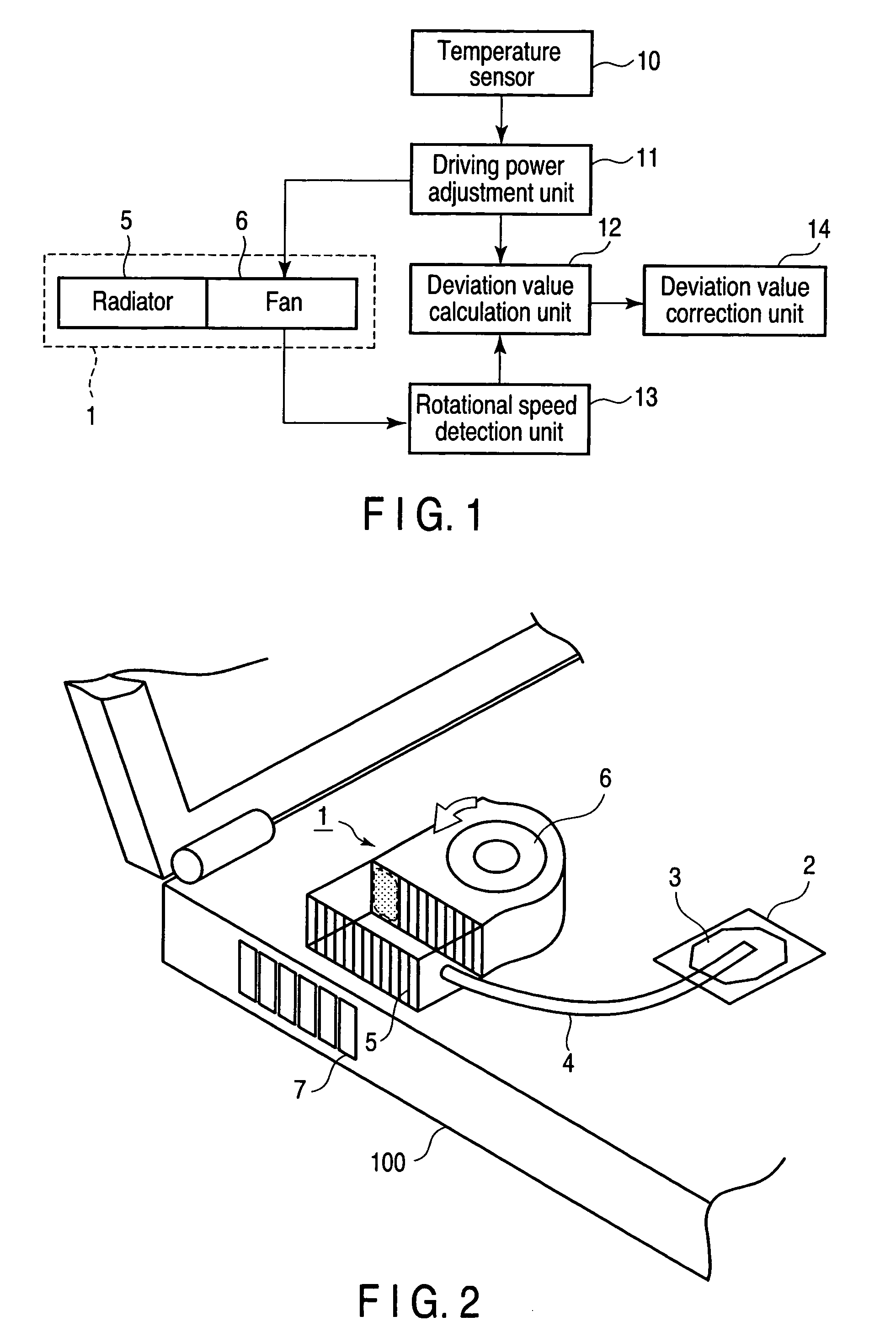
[0030]FIG. 1 is a block diagram of an electronic device having a cooling performance degradation detecting function according to the first embodiment. FIG. 2 illustrates the outer appearance of a cooling unit provided inside the case of an electronic device 100.

[0031]A cooling unit 1 includes a radiator 5 which dissipates heat transported from a heat generating portion 2 such as a CPU via a heated portion 3 and a heat pipe 4, and a fan 6 which rotates and sends air to the radiator 5 according to driving power. The radiator 5 is cooled by air sent from the fan 6.

[0032]A driving power adjustment unit 11 adjusts the driving power to be input to the fan 6 in accordance with the temperature of the heat generating portion 2 measured by a temperature sensor 10 incorporated in the CPU and a driving condition corresponding to the measured temperature. If the fan 6 employs, e.g., constant voltage PWM control, the driving power adjustment unit 11 adjusts the PWM signal to be output to the fan ...

second embodiment

[0058]FIG. 7 is a block diagram of an electronic device according to the second embodiment. The electronic device shown in FIG. 7 is formed by adding an operating time recording unit 16 to an electronic device 100 shown in FIG. 1. The same reference numbers as in FIG. 1 denote the same parts in FIG. 7, and a description thereof will be omitted.

[0059]The operating time recording unit 16 records the sum of the operating times of a fan 6. Correction is done using an aging expression (performance estimating expression) of the rotational speed of the fan 6 using the sum as a variable. The performance estimating expression may give a temporal decrease amount of the rotational speed at a predetermined duty ratio or a temporal increase amount of the duty ratio at a predetermined rotational speed. For example, in (1) of the first embodiment, the difference between the duty ratio at a predetermined rotational speed in the first use and that at a given timing is defined as a value s in X=a+s. ...

third embodiment

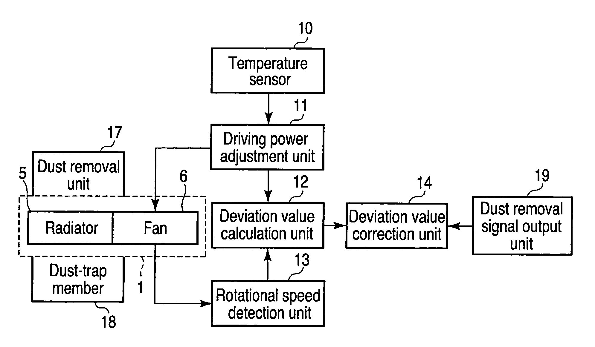
[0060]FIG. 8 is a block diagram of an electronic device according to the third embodiment. The electronic device shown in FIG. 8 is formed by adding a dust removal unit 17 and a dust removal signal output unit 19 to an electronic device 100 shown in FIG. 1. The same reference numbers as in FIG. 1 denote the same parts in FIG. 8, and a description thereof will be omitted.

[0061]Upon detecting dust clogging based on a calculated deviation value, a deviation value calculation unit 12 instructs the user to operate the dust removal unit 17. This operation may automatically be done by causing an internal unit of the electronic device or another electronic device connected via a network to issue an instruction.

[0062]FIGS. 9 and 10 are views showing the dust removal unit 17. A hinge 21 which rotatably connects a display 20 to the case of the electronic device 100 may have a rotation spring or gear attached to it. The hinge 21 has a driving rod 22 which rotates as the display 20 opens or clos...


PUM


Abstract

An electronic device includes a deviation value calculation unit which calculates a deviation value from the normal boundary of the relationship between a power index associated with the driving power and the measured rotational speed of the fan, a clogging detection unit which detects, based on the deviation value, clogging in an air duct through which the fan takes in air outside the case and sends it to the radiator, and a deviation value correction unit which corrects the deviation value in accordance with aging of performance of the fan to compensate for deterioration of the clogging detection capability of the clogging detection unit caused by the aging.

Description

CROSS-REFERENCE TO RELATED APPLICATIONS[0001]This application is based upon and claims the benefit of priority from prior Japanese Patent Application No. 2008-143237, filed May 30, 2008, the entire contents of which are incorporated herein by reference.BACKGROUND OF THE INVENTION[0002]1. Field of the Invention[0003]The present invention relates to an electronic device such as a notebook personal computer equipped with a cooling unit including a radiator and a fan and, more particularly, to an electronic device which detects performance degradation of a cooling unit.[0004]2. Description of the Related Art[0005]An electronic device such as a notebook personal computer commonly uses a cooling unit including a heat disperser, heat pipe, radiator, and fan to cool a heat generating portion such as a CPU. Heat from the heat generating portion is transferred to the heat disperser that is in contact with it and transported to the radiator through the heat pipe. The fan takes in air from an o...

Claims


Application Information

Patent Timeline
Patent Type & Authority Patents(United States)
IPC IPC(8): G05D23/00F01P7/14F28F27/00
CPCG05B23/0235G05D23/19H05K7/20209G05B2219/24077H01L2924/0002H01L2924/00
Inventor KITAMURA, HIDEOHIROHATA, KENJIHISANO, KATSUMITAKAMATSU, TOMONAO
Owner KK TOSHIBA
Why Eureka
Try Eureka