Reconfigurable circuit having a pipeline structure for carrying out time division multiple processing

a reconfigurable circuit and pipeline structure technology, applied in the field of dynamic reconfigurable circuits, can solve the problems of increasing processing time from data input to data output, time overhead generation, etc., and achieve the effect of reducing the latency of data input/outpu

Active Publication Date: 2011-11-08
FUJITSU LTD
View PDF15 Cites 44 Cited by
  • Summary
  • Abstract
  • Description
  • Claims
  • Application Information

AI Technical Summary

Benefits of technology

[0011]The purpose of the present invention is to provide a reconfigurable circuit in which time division multiple processing is possible, and the time loss arising from the switching of the aforesaid configuration and the latency of data input / output are decreased.
[0020]The present invention provides, in another way, the first reconfigurable circuit, the second reconfigurable circuit in which a lag of a configuration switching cycle exists between the first reconfigurable circuit and the second reconfigurable circuit, and a reconfigurable circuit which is inserted between the network of the first reconfigurable circuit and the network of the second reconfigurable circuit and is equipped with the delay unit for adjusting the lag of a configuration switching cycle to make reconfiguration and parallel processing possible.
[0021]According to the present invention, it is possible to obtain a reconfigurable circuit in which time division multiple processing is possible, and the time loss a rising from the switching of the aforesaid configuration and the latency of data input / output are decreased.

Problems solved by technology

On the other hand, in the method in which the configuration is switched to perform a plurality of processes in a time division way, time overheads are generated due to the interruption of the pipeline processing occurring when the configuration is switched.
Furthermore, buffer processing of input / output data for retract processing is also required, so that the processing time from data input to data output (latency) increases.

Method used


Image

  • Reconfigurable circuit having a pipeline structure for carrying out time division multiple processing
  • Reconfigurable circuit having a pipeline structure for carrying out time division multiple processing
  • Reconfigurable circuit having a pipeline structure for carrying out time division multiple processing

Examples


first embodiment

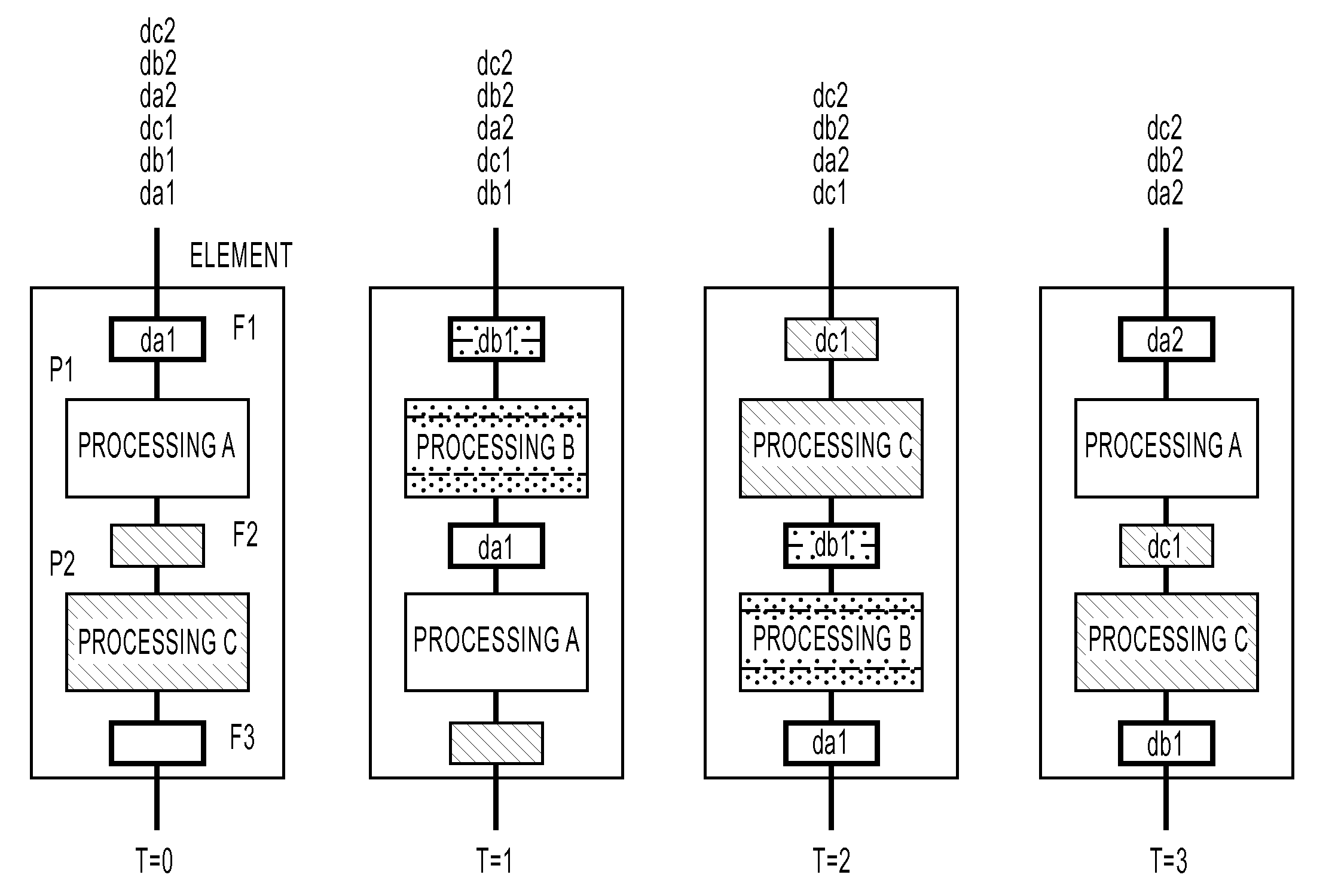
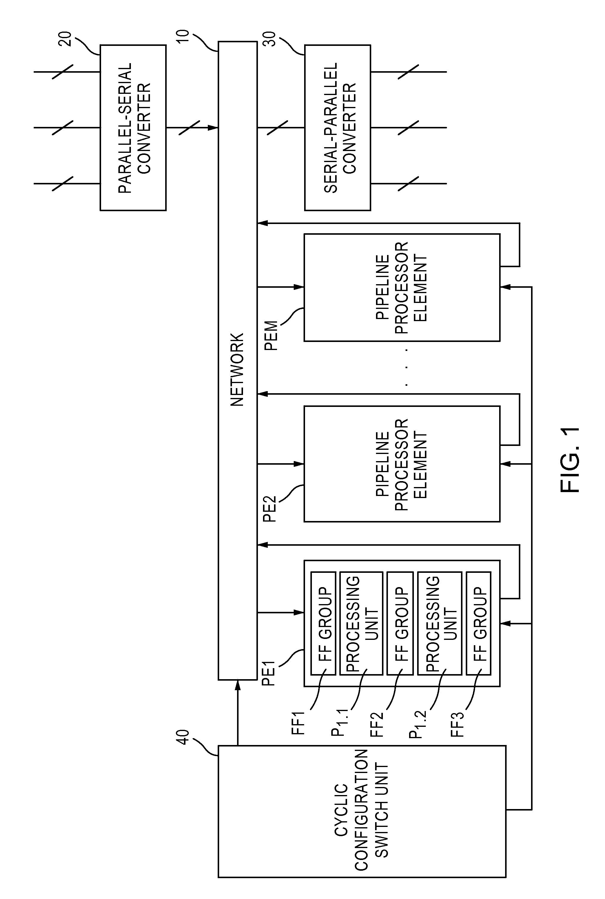
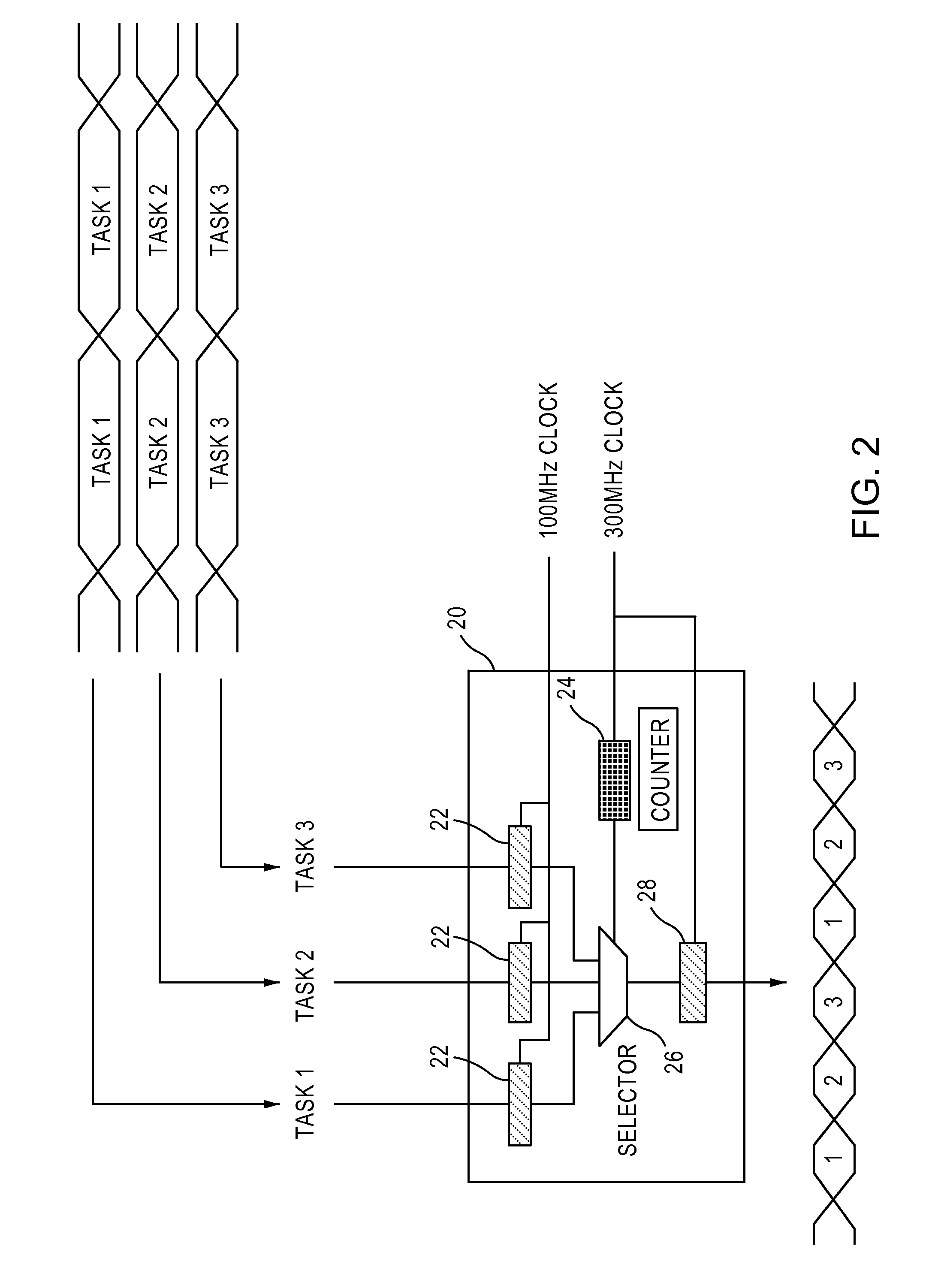
[0037]FIG. 1 is a block diagram showing the concept of the configuration of a reconfigurable circuit in which time division multiple processing is possible according to a first embodiment of the present invention. In FIG. 1, the reconfigurable circuit 1 (hereinafter referred to as “processor 1”) comprises a plurality of processor elements {PEi|i=1, 2, . . . , M} (M is the number of processor elements), a network 10 in which the input and output of each processor element PEi are connected, a parallel / serial converter 20 which captures a plurality of input data into the network 10 by means of time division multiplexing, a serial / parallel converter 30 which outputs the output data from arbitrary processor elements PEi, PEj and PEk (1≦i, j, k≦M) which are transferred from the network 10 by means of time division multiplexing to the output terminals corresponding to processor elements PEi, PEj and PEk, and a cyclic configuration switching unit 40 which supplies configuration data definin...


PUM


Abstract

The reconfigurable circuit of the present invention in which time division multiple processing is possible has a pipeline structure with the number of stages of an integral multiple of a given number, and comprises a plurality of processor elements having a processing unit whose configuration is variable according to first configuration data to be supplied, a network in which all inputs and outputs of a plurality of said processor elements are connected and which transfers data by one clock between the input and output according to second configuration data to be supplied, and a switching unit which cyclically switches by one clock and supplies the first and second configuration data prepared for the given number of tasks to each of the processing units.

Description

CROSS-REFERENCE TO RELATED APPLICATIONS[0001]This application is based upon and claims the benefit of priority from the prior Japanese Patent Application No. 2004-195042, filed in Jun. 30, 2004, the entire contents of which are incorporated herein by reference.BACKGROUND OF THE INVENTION[0002]1. Field of the Invention[0003]The present invention relates to a dynamic reconfigurable circuit in which time division multiple processing is possible.[0004]2. Description of the Related Art[0005]The present invention relates to a reconfigurable circuit constituted by a network connecting a processor element and a processor element which process data. The reconfigurable circuit executes various kinds of functions at the speed equivalent to an ASIC by rewriting the configuration data which defines the operation of a circuit in terms of software. Therefore, various kinds of applications (tasks) can be executed in the same reconfigurable circuit. However, with the progress of circuit technology, ...

Claims


Application Information

Patent Timeline
Patent Type & Authority Patents(United States)
IPC IPC(8): G06F15/76
CPCG06F9/3885G06F9/3897G06F15/7867G06F15/8015
Inventor FUJISAWA, HISANORIYOSIZAWA, HIDEKIISHIHARA, TERUO
Owner FUJITSU LTD
Why Eureka
Try Eureka