Foam pump assembly

a technology of foam pump and assembly, which is applied in the direction of instruments, liquid transfer devices, single-unit apparatuses, etc., can solve the problems of difficult fabrication, more susceptible to and at least partly clogging of porous parts

Active Publication Date: 2011-11-15
ECOLAB USA INC
View PDF41 Cites 22 Cited by
  • Summary
  • Abstract
  • Description
  • Claims
  • Application Information

AI Technical Summary

Benefits of technology

It is an object of the present invention to provide a foam pump assembly which provides a good foam product without any porous member.

Problems solved by technology

However, such a porous member can become at least partly clogged when the mixture oxidizes or dries out, especially when the pump is unused for an extended period.
Although the mesh pore size may be different for different applications, the pore size is typically relatively small which tends to make the porous member more susceptible to clogging.
The porous member may also be difficult to fabricate and may also make the pump more costly.

Method used


Image

  • Foam pump assembly
  • Foam pump assembly
  • Foam pump assembly

Examples


Embodiment Construction

A preferred exemplary embodiment of the invention will now be described, but the invention is not limited to this embodiment.

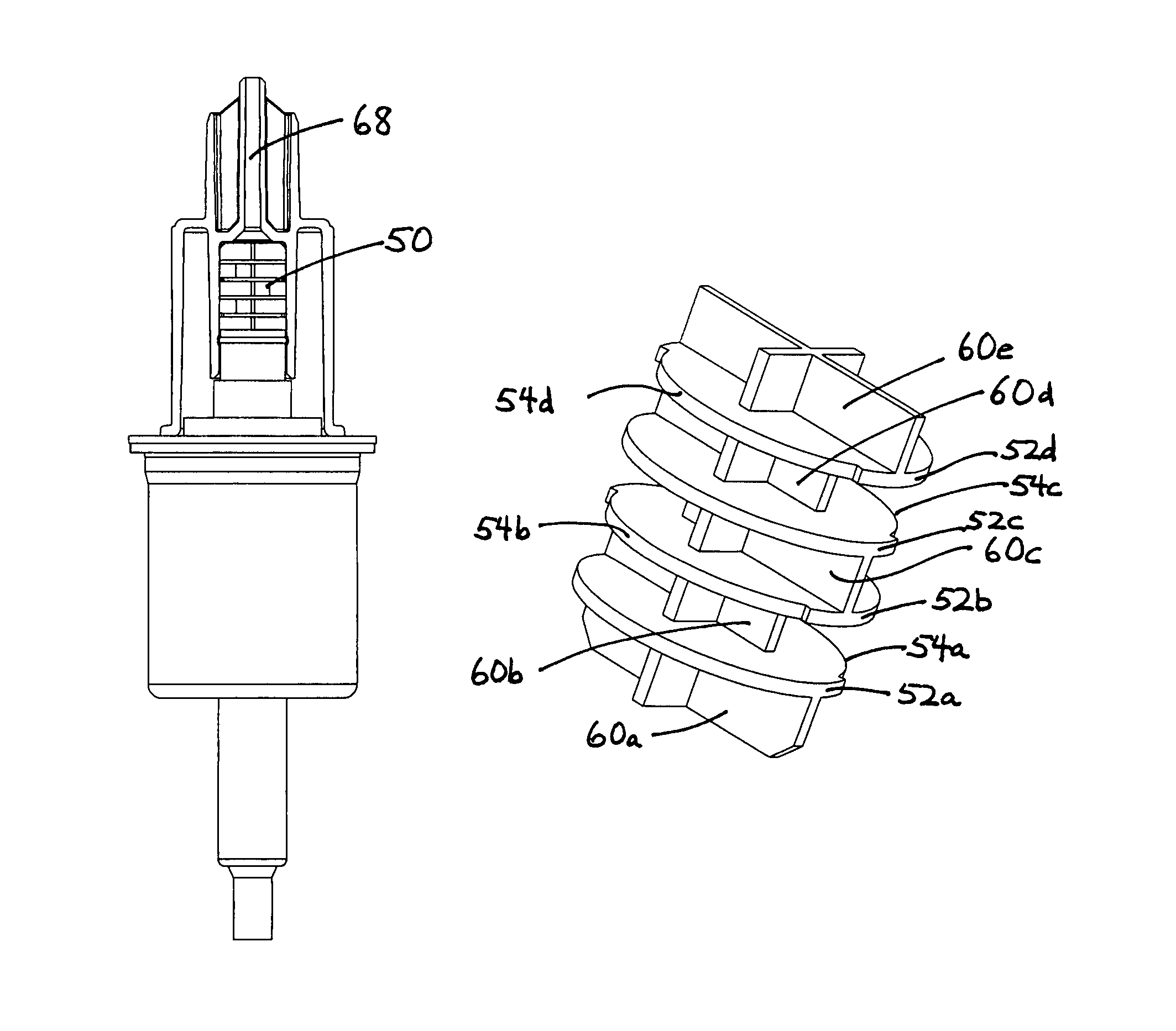
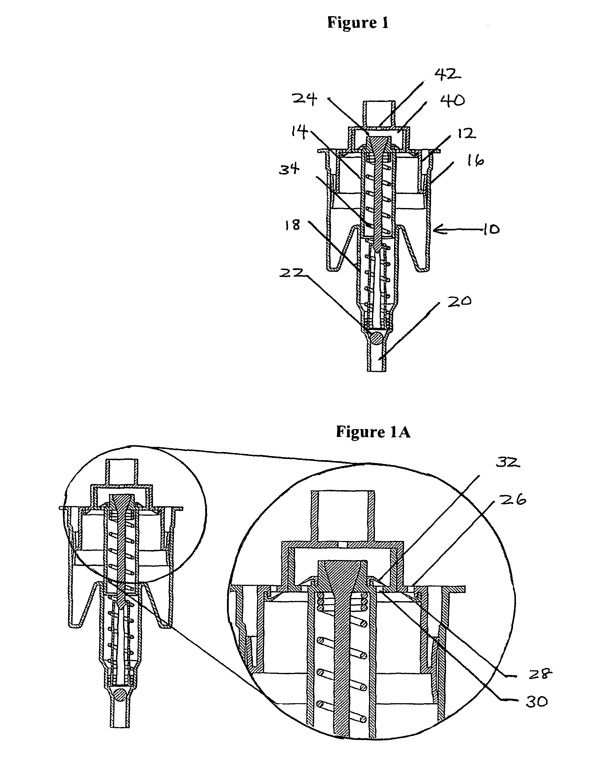
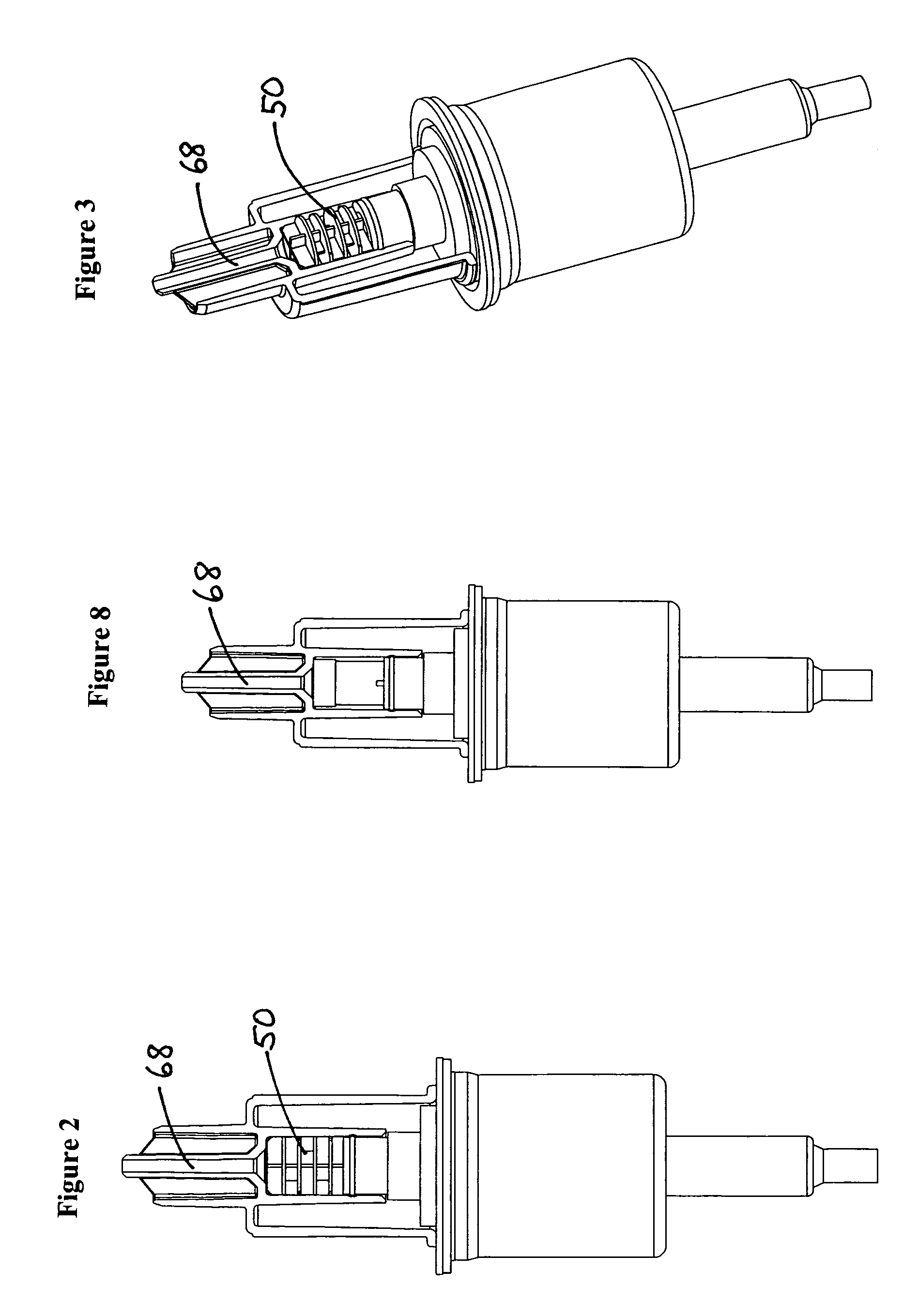
The invention provides a foam pump assembly for dispensing foam, comprising a dual piston pump engine having an air cylinder and fluid cylinder, said cylinders having an air piston and a liquid piston, respectively, said liquid cylinder having a liquid inlet valve and a liquid outlet valve, said air cylinder having an air inlet valve and an air outlet, a mixing chamber in communication with the liquid cylinder through the liquid outlet valve for receiving liquid, and in communication with the air cylinder through the air outlet for receiving air, an outlet chamber in communication with the mixing chamber and in communication with a pump outlet for dispensing foam, said outlet chamber providing a flow path with successive turns, whereby when air and fluid is fed into said mixing chamber foam is created which passes into the outlet chamber, through the flow path...


PUM


Abstract

A foam pump assembly for dispensing foam comprises a dual piston pump engine having an air cylinder and fluid cylinder each with pistons, a mixing chamber in communication with the liquid cylinder for receiving liquid, and in communication with the air cylinder for receiving air, an outlet chamber providing a flow path with turns, whereby when air and fluid is fed into said mixing chamber foam is created which passes into the outlet chamber, through the flow path and out of the pump outlet.

Description

BACKGROUND OF THE INVENTIONThe present invention relates to a foam pump assembly usable to make foam for use as personal care and / or hygiene products such as hand soap, moisturizers, sanitizers, shampoo, shower gels, and shaving cream, for example.There are a number of commercial foam pumps and pump engines on the market today available from companies such as Arminak and Associates, Airspray, K&K, and others. Some patents relating to such foam pumps are U.S. Pat. Nos. 5,271,530; 5,443,569; 5,445,288; 6,053,364 and 6,082,586, all of which are incorporated by reference herein. Such foam pumps typically comprise a pump engine connected to a liquid container. The overall assembly typically has an air chamber with an air inlet and air outlet, a liquid chamber with a liquid inlet and liquid outlet, a mixing chamber, an actuator for working the pump so that air from the air chamber and liquid from the liquid chamber is fed to the mixing chamber to create foam. These pumps typically have a ...

Claims


Application Information

Patent Timeline
Patent Type & Authority Patents(United States)
IPC IPC(8): B67D7/76B67D7/78
CPCA47K5/14B05B7/0043B05B11/3087B05B11/1087
Inventor SNODGRASS, DAVID L.
Owner ECOLAB USA INC
Why Eureka
Try Eureka