Gas mixing and dispersement in pumps for pumping molten metal

a technology of gas mixing and dispersing in pumps and molten metal, which is applied in the field of pumps, can solve the problems of counterbalancing the detrimental effects of cavitation in the gas/molten metal mixing chamber, disadvantageous pumps and pump components, etc., and achieves the effects of reducing production costs, reducing cavitation, and pumped more efficiently

Inactive Publication Date: 2009-01-13
THUT BRUNO H
View PDF73 Cites 112 Cited by
  • Summary
  • Abstract
  • Description
  • Claims
  • Application Information

AI Technical Summary

Benefits of technology

[0007]Gas that is directed into the mixing chamber can cause cavitation. Cavitation is normally disadvantageous to pumps and pump components due to the wear or damage it imposes on them. However, while not wanting to be bound by theory, in the present invention the detrimental effects of cavitation in the gas / molten metal mixing chamber are counterbalanced by rotating the impeller in the pumping chamber where there is no significant cavitation. Even if there are some detrimental effects of cavitation in the mixing chamber, it is expected to be minimal. The invention is believed to provide superior mixing of gas and molten metal and pumping efficiency compared to the gas injection pump system where gas is injected at the discharge of the base. Thus, the invention may provide economic and performance advantages compared to gas injection pumps that are currently on the market.
[0009]A gas conduit extends from a gas source and has an outlet located at the inlet protector for directing gas into the impeller chamber. Alternatively, the gas conduit may extend directly into the base. Near the outlet of the gas conduit is disposed a porous gas dispersement member composed of porous graphite, sintered silicon carbide or other suitable porous refractory material adapted to disperse gas from the gas conduit. The dispersement of the gas reduces or eliminates cavitation in the impeller chamber.
[0014]The present invention offers numerous advantages. Molten metal can be pumped more efficiently leading to more economical production of metal articles. More efficient mixing of the gas and the molten metal may reduce the cost of production by using less gas. The invention also may reduce liberation of toxic chlorine gas, providing a safer work environment.

Problems solved by technology

Gas that is directed into the mixing chamber can cause cavitation.
Cavitation is normally disadvantageous to pumps and pump components due to the wear or damage it imposes on them.
However, while not wanting to be bound by theory, in the present invention the detrimental effects of cavitation in the gas / molten metal mixing chamber are counterbalanced by rotating the impeller in the pumping chamber where there is no significant cavitation.

Method used


Image

  • Gas mixing and dispersement in pumps for pumping molten metal
  • Gas mixing and dispersement in pumps for pumping molten metal
  • Gas mixing and dispersement in pumps for pumping molten metal

Examples


Embodiment Construction

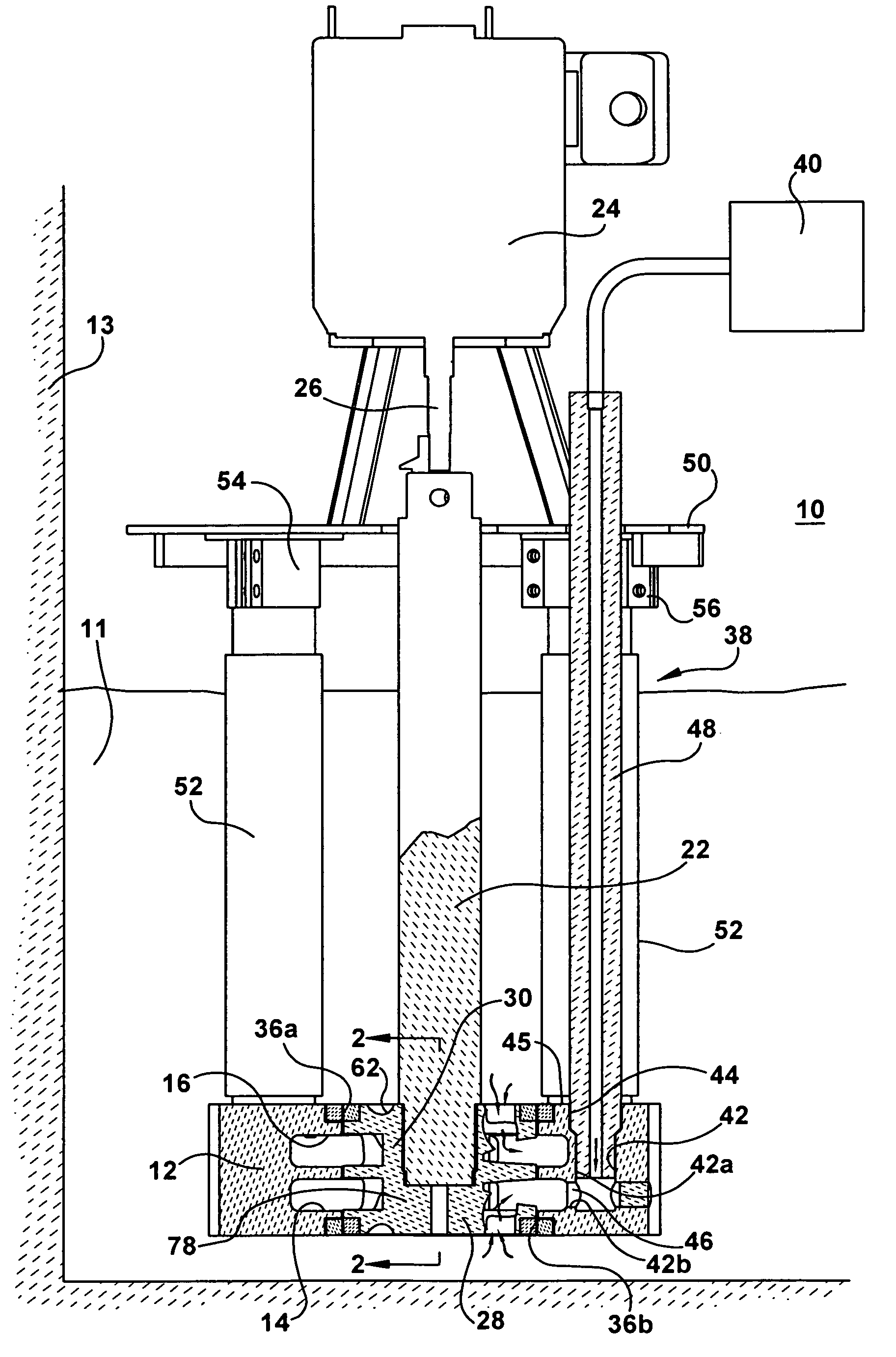
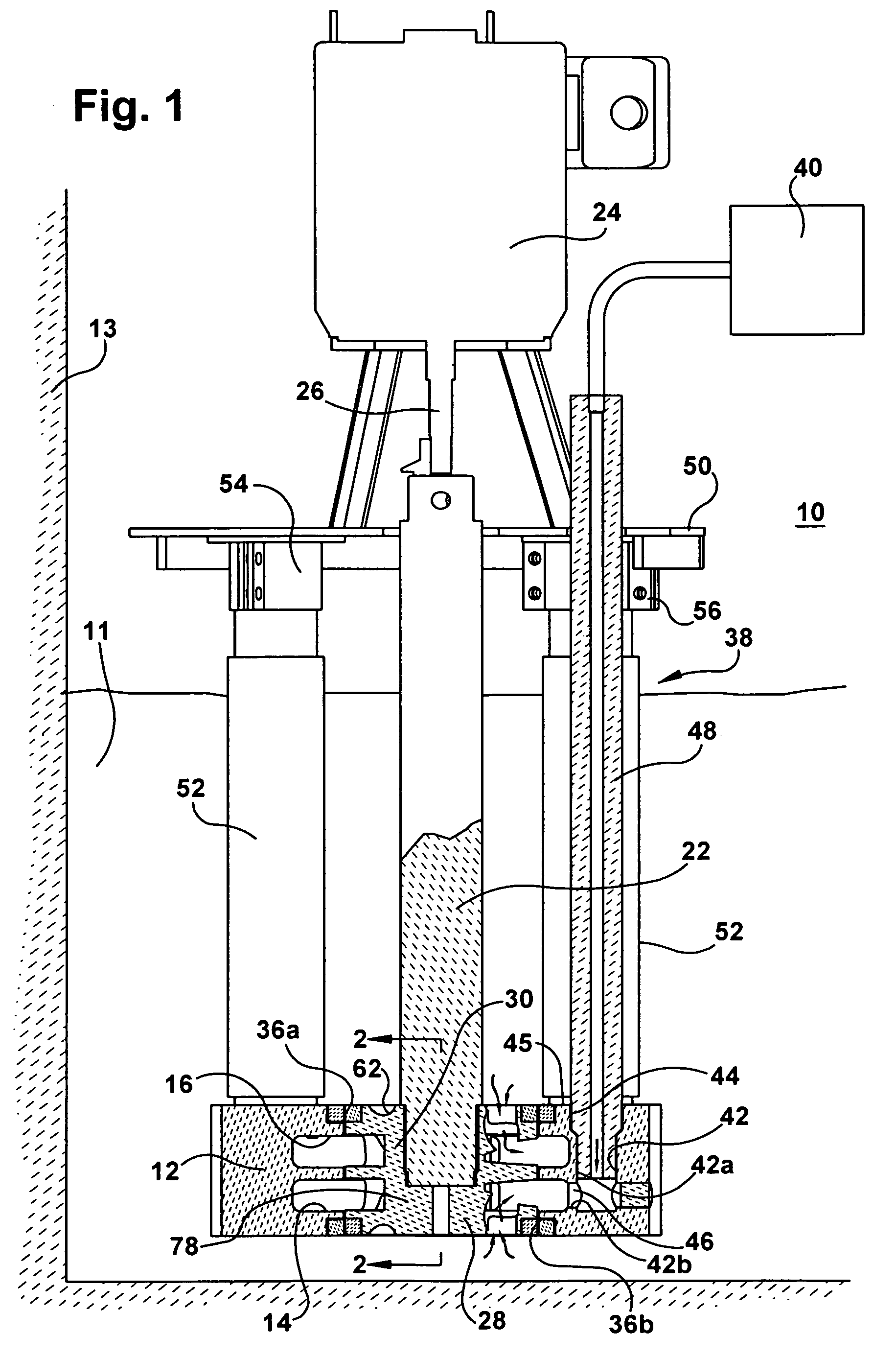
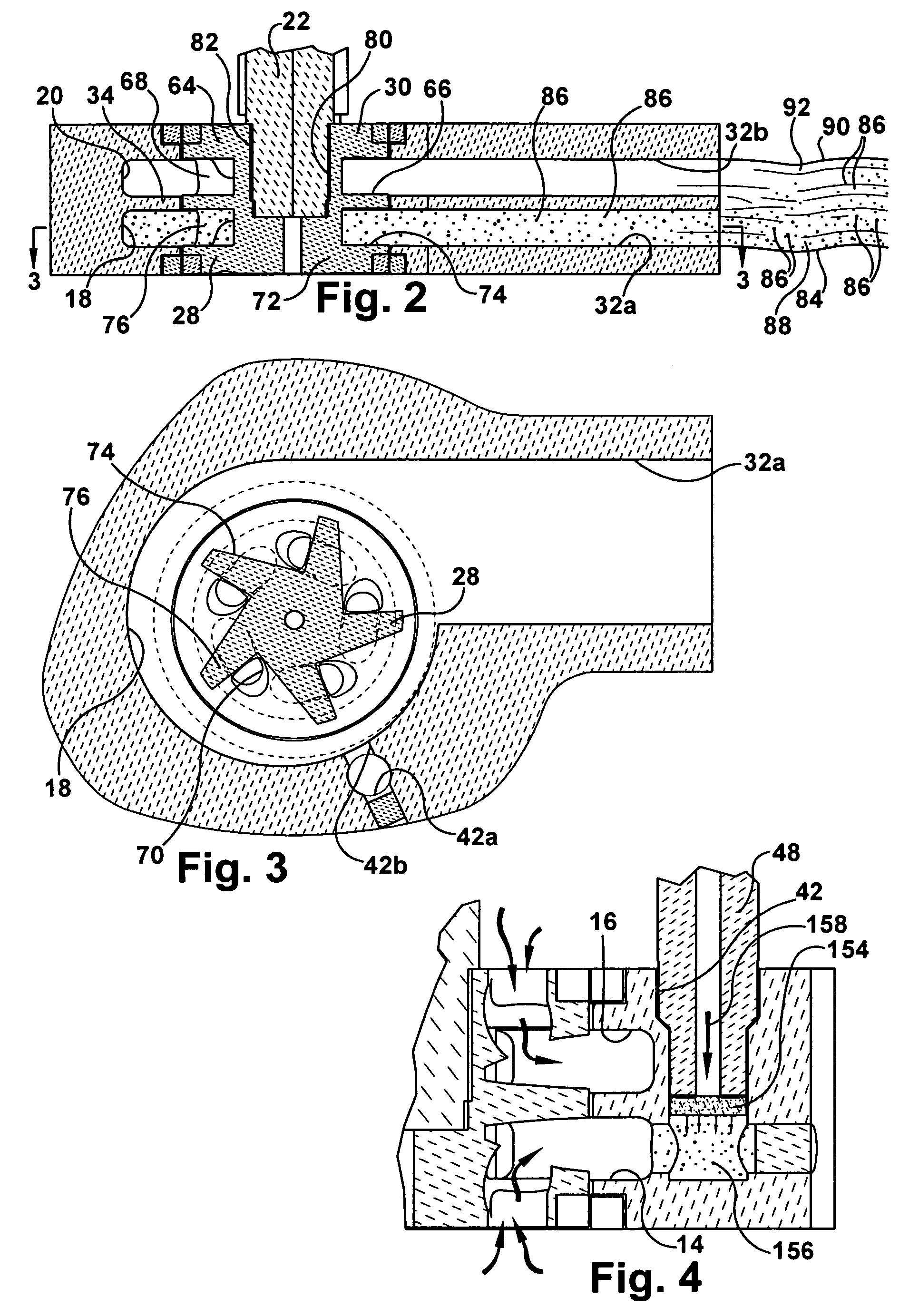
[0022]Referring now to the drawings, FIG. 1 shows a pump 10 for gas / molten metal mixing and molten metal pumping. The pump has a base 12 submerged in a bath of molten metal 11 contained by a vessel 13. The base includes a gas / molten metal mixing impeller chamber 14 and a molten metal pumping impeller chamber 16. A volute 18 forms a part of the mixing chamber and a volute 20 forms a part of the pumping chamber (FIG. 2). A shaft 22 is rotatably driven by a motor 24. A motor drive shaft 26 is coupled to the shaft 22 in a known manner. Impeller members 28, 30 connected to the shaft are located in the mixing chamber 14 and pumping chamber 16, respectively. The pump includes an outlet formed by a first discharge passageway 32a extending from the mixing impeller chamber and a second discharge passageway 32b extending from the pumping impeller chamber (FIG. 2). In this example, the first and second discharge passageways are configured and arranged the same. The mixing and pumping chambers a...


PUM

PropertyMeasurementUnit
forceaaaaaaaaaa
pumping flow ratesaaaaaaaaaa
refractoryaaaaaaaaaa

Abstract

A molten metal pump including a pump base with an inlet and outlet, a mixing impeller chamber for mixing gas and molten metal, a pumping impeller chamber for pumping molten metal. First and second impeller members supported by a shaft are adapted to rotate in mixing and pumping chambers respectively. The impeller members may be integrally formed of a single impeller or separate impellers on one or more shafts. A gas passageway extends from a gas source to the mixing chamber in the base. A gas dispersement pump includes a base with an impeller chamber and inlet and an outlet. An impeller is mounted to a shaft and adapted to be rotated in the impeller chamber. A gas passageway extends from a gas source to a gas outlet proximate to the impeller chamber. A gas dispersement member of porous refractory material is adapted to disperse gas from the gas passageway. In a gas dispersement and gas / molten metal mixing pump, the dispersement member disperses the gas stream entering the mixing chamber where the gas is mixed with molten metal. Molten metal is pumped in the pumping chamber. A gas / molten metal mixture is discharged from the mixing chamber and molten metal is discharged from the pumping chamber.

Description

I. FIELD OF THE INVENTION[0001]The invention relates to the field of pumps designed to pump molten metal and to treat the molten metal with gas.II. BACKGROUND OF THE INVENTION[0002]One type of pump for pumping molten metal rotates an impeller on the end of a shaft inside an impeller chamber of a base submerged in the molten metal. The impeller chamber may include a volute or may be a nonvolute chamber as disclosed in U.S. Pat. No. 5,203,681. The pump may be used to circulate molten metal or to transfer molten metal. In a circulation pump, a discharge passageway extends from the impeller chamber to an exterior surface of the base. In a transfer pump, the base includes a socket that receives a riser or conduit that extends to another location where it is desired to move the molten metal. The discharge passageway extends from the impeller chamber to the socket.[0003]It has been proposed to introduce reactive and / or inert gas into molten metal for various metallurgical and processing pu...

Claims


Application Information

Patent Timeline
Patent Type & Authority Patents(United States)
IPC IPC(8): C21C7/072
CPCC21C1/06C21C7/072C22B9/05C22B9/055C22B21/064F27D3/14
Inventor THUT, BRUNO H.
Owner THUT BRUNO H
Why Eureka
Try Eureka