Method and device for feeding components for bone cement into a mixing vessel

a technology of bone cement and components, which is applied in the direction of mixing methods, mixers, diagnostics, etc., can solve the problems of environmental harm and human health harm, and achieve the effect of avoiding the risk of gas releas

Inactive Publication Date: 2006-07-11
CEMVAC SYST
View PDF26 Cites 113 Cited by
  • Summary
  • Abstract
  • Description
  • Claims
  • Application Information

AI Technical Summary

Benefits of technology

[0006]The object of the present invention is to make available a method and device of the kind described above, which avoids the risk of gas release when feeding the bone cement components into the mixing vessel. This is achieved in accordance with the invention in a number of ways. According to one method, a glass ampoule containing a liquid component of a bone cement is surrounded by a container which is in reclosable communication with the atmosphere. A second container surrounds the first container so that when the mixing vessel is opened, the contents of the ampoule, under the effect of a partial vacuum inside the mixing vessel, can be sucked down into it, in that a space between the aforementioned inner container and outer container is filled with a second bone cement component in powder form which is caused by displacement of the inner container relative to the outer container, to move from a first position in which the space does not communicate with the atmosphere or the mixing vessel, then to a second position in which the space communicates with the atmosphere and the mixing vessel, so that the powdered bone cement component is sucked down into the mixing vessel under the effect of the partial vacuum inside it.
[0007]A device for carrying out the above method in accordance with the invention is characterized in that it comprises an inner container communicating with the atmosphere, and is so arranged as to enclose the glass ampoule containing the liquid bone cement component, and to communicate with the aforementioned mixing vessel, and which includes means for opening the ampoule so that its contents, under the effect of the partial vacuum inside the mixing vessel, can be sucked into it. The outer container at least partially encloses the inner container and is also arranged so as to communicate with the mixing vessel and together with the inner container, defines a space therebetween which is filled with a certain quantity of the powdered component of the bone cement. The inner container is capable of displacement from a first position to a second position, the first position characterized by the inner container preventing communication between both the mixing vessel and the atmosphere, and the second position characterized, in which communication between the mixing vessel on the one hand the the atmosphere on the other hand is open, so that the bone cement component in powder form, under the effect of the partial vacuum inside the mixing vessel, can be sucked into it without escape of gases.

Problems solved by technology

Both the liquid component and the combined mixture give off substances in gaseous form which are environmentally harmful and injurious to human health.

Method used


Image

  • Method and device for feeding components for bone cement into a mixing vessel
  • Method and device for feeding components for bone cement into a mixing vessel
  • Method and device for feeding components for bone cement into a mixing vessel

Examples


first embodiment

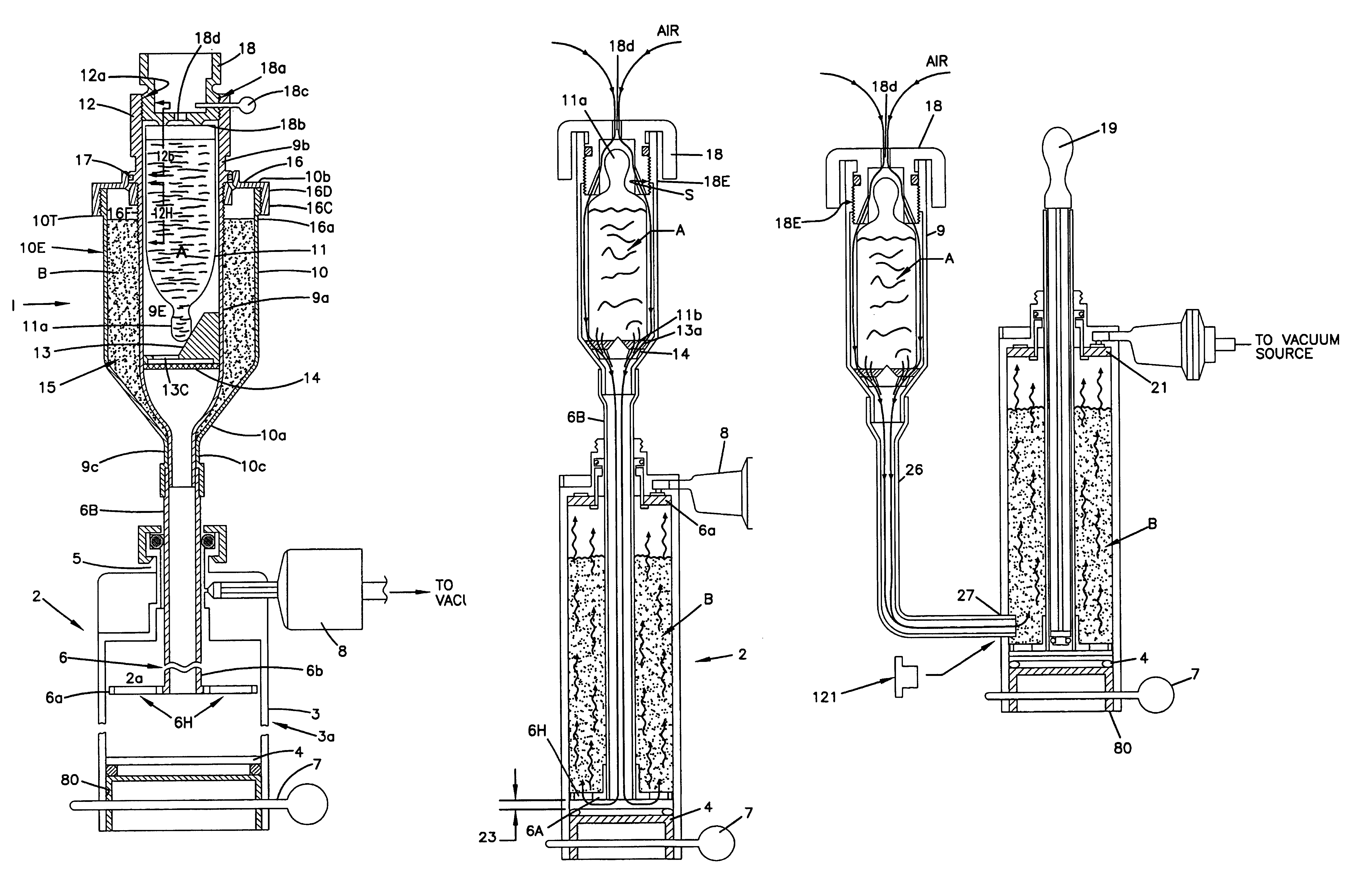
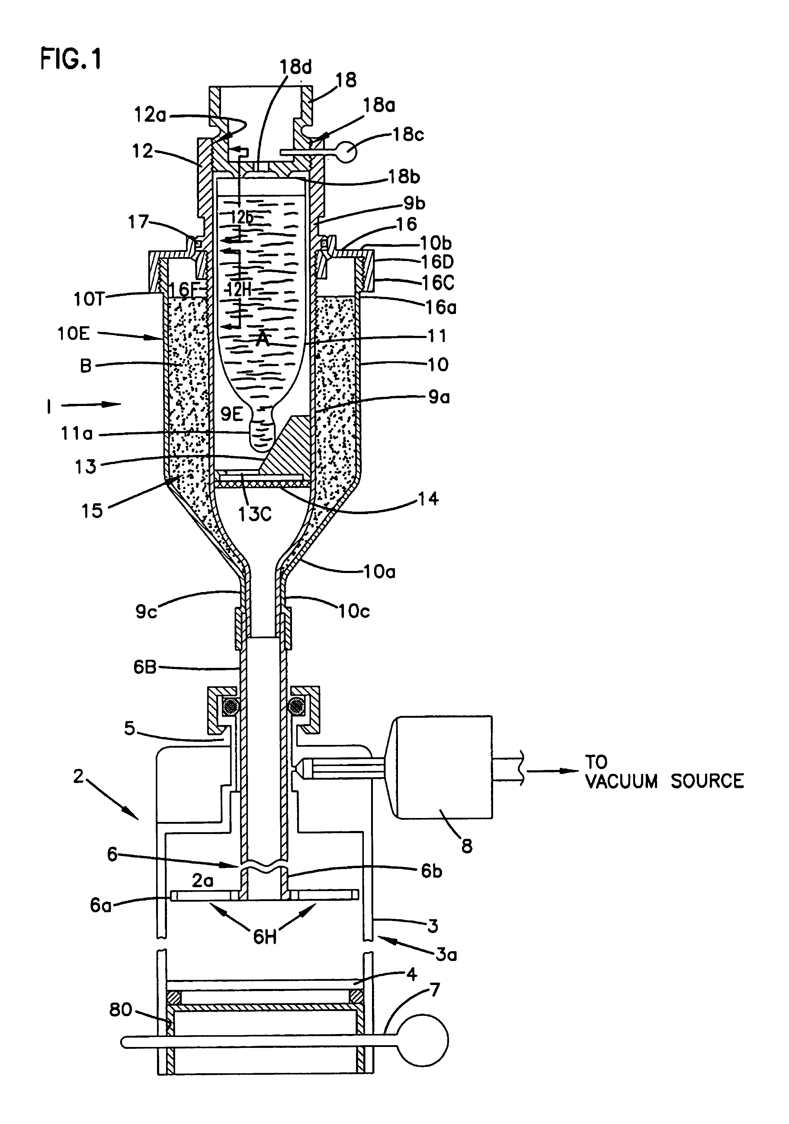
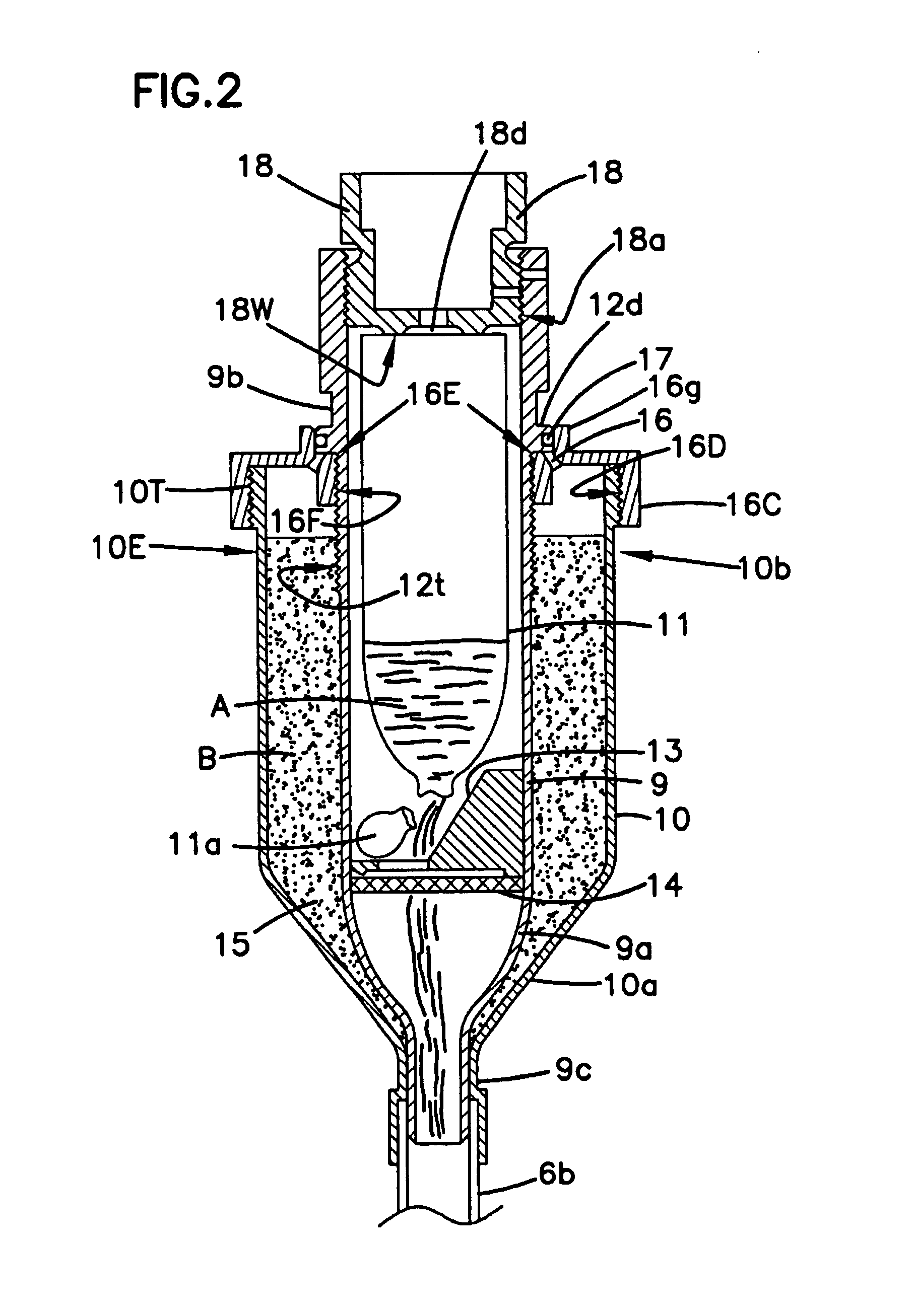
[0034]The feed arrangement 1 of the first embodiment, shown in FIGS. 1-3, comprises an inner, essentially cylindrical container 9 communicating with the atmosphere and an outer, similar cylindrical container 10 which at least partially encloses the inner container. The container interior 9e is so arranged so as to enclose a glass ampoule 11 containing the liquid bone cement component A, and to communicate with the mixing vessel 2, via its agitator rod 6b, as already mentioned. The container 9 is integrally formed having a cylindrical collar 12 about its bottom end 9b with a threadable cap 18 capable of axial displacement relative to it. Removal of cap 18 allows insertion of ampoule 11 within interior 9e.

[0035]In the embodiment illustrated in FIG. 1, the facility for displacement to take place between the cylindrical collar 12 and the cap 18 is achieved by means of the internal collar threads 12a engaging the external cap threads 18a. The cap 18 has an opening 18d communicating betw...

third embodiment

[0037]The third embodiment in accordance with FIG. 6, shows that the only difference between this embodiment and the embodiments of FIGS. 4 and 5, is found in the brush-shaped devices 9d which are arranged as to make contact with the surface of the funnel-shaped part 10a in the first position of container 9. The bone cement component B is released from the aforementioned surface by relative rotation between the outer and inner containers such that trushes 10d, under weight of the powder, collapse and allow powder to fall into tube 6b.

[0038]A feed procedure of the above-described embodiments will now be summarized below with reference to FIGS. 1-6 of the drawings. It should be understood that with these embodiments, the feed arrangement is supplied ready for use, meaning it is filled with the bone cement components in the correct proportions.

[0039]As FIG. 1 illustrates, in order to permit feeding of the bone cement components into the mixing vessel 2 from the feed arrangement 1 in a...

fourth embodiment

[0042]In accordance with the fourth embodiment, FIGS. 7-11 show mixing vessel 2 as being pre-filled with the powder component of the bone cement. A tightening rod 19 is received within tubular agitator rod 6b of agitator 6 and has plug 19a and O-ring 19c inserted within a groove 19b thereof, to form an air-tight seal so that powdered contents B are not contacted by and affected by atmospheric air which is capable of downwardly travelling along tubular rod 6b to vessel bottom 4. Just prior to introducing glass ampoule 11 on top of mixing vessel 2, tightening rod 19 is completely removed from tube 6b, wherein the cylindrical container 9 is placed on top of vessel 2 by inserting funnel-shaped neck 9c into mouth 6c at the first end 6d of tubular rod 6b. Although FIGS. 1-6 show funnel-shaped top end 9a as having a slightly different contour from that of the same section shown in FIGS. 7-12, it should be understood that either contour can be used interchangeably in these embodiments. FIG....


PUM

PropertyMeasurementUnit
vacuumaaaaaaaaaa
optimal strengthaaaaaaaaaa
displacementaaaaaaaaaa

Abstract

A method and an arrangement for successively feeding batches into a mixing vessel under partial vacuum for the preparation of bone cement. The arrangement includes an inner container communicating with the atmosphere and with the mixing vessel, which container is so arranged as to enclose a glass ampoule containing a liquid bone cement component and, on the other hand, a device for opening the ampoule so that its contents can be sucked into the mixing vessel under partial vacuum. An outer container encloses the inner container at least partially, and is arranged to communicate with the mixing vessel. The inner container, and the outer container, define a space filled with a proportional quantity of a second bone cement component, which is in powder form. The inner container is capable of displacement relative to the outer container between a first position, in which sections of the inner container prevent communication between the mixing vessel and the atmosphere, and a second position, in which communication between both the mixing vessel and the atmosphere is open, so that the powdered bone cement component can be sucked into the mixing chamber under vacuum. The feeding sequence of the bone cement components is arbitrary. In other embodiments, the inner and outer containers are eliminated, or only the inner container is retained.

Description

[0001]This application is a continuation of application Ser. No. 08 / 734,817, filed Oct. 22, 1996, now abandoned, which is a continuation-in-part of Ser. No. 08 / 545,591 filed Nov. 13, 1995, now abandoned which is based on PCT / SE94 / 00415 filed May 6, 1994.BACKGROUND OF THE INVENTION[0002]1. Field of the Invention[0003]The present invention relates to a method for successively feeding batches of constituent components into a mixing vessel for the preparation of bone cement under vacuum. The invention also relates to an apparatus for successively feeding batches of constituent components into a mixing vessel under partial vacuum for the preparation of bone cement.[0004]2. Description of the Prior Art[0005]Bone cement is prepared by mixing polymethyl methacrylate in powder form with liquid monomethylmethacrylate in a mixing container. Both the liquid component and the combined mixture give off substances in gaseous form which are environmentally harmful and injurious to human health. For...

Claims


Application Information

Patent Timeline
Patent Type & Authority Patents(United States)
IPC IPC(8): B01F13/06B01F15/02A61B19/02A61F2/00A61F2/46B01F3/12B01F11/00B01F13/00
CPCB01F15/0226B01F11/0082B01F13/002B01F13/06B01F15/0205B01F15/0206B01F15/0223B01F15/0234B01F15/0258B01F15/0278B01F15/0224B01F15/0215A61B17/8827A61F2002/30561A61F2002/4685A61F2250/0071B01F15/0266B01F2003/1257B01F2215/0029A61B2019/0218A61B2050/0064B01F23/565B01F31/441B01F33/5011B01F33/70B01F35/713B01F35/7131B01F35/7139B01F35/7161B01F35/7162B01F35/7164B01F35/7173B01F35/718B01F35/75B01F35/754251B01F2101/20
Inventor JONSSON, SOREN
Owner CEMVAC SYST
Why Eureka
Try Eureka