
Expandable mandrel for use in friction stir welding

a mandrel and friction stir technology, which is applied in the direction of auxillary welding devices, forging/pressing/hammering apparatus, shape tools, etc., can solve the problems of non-fusion weldability, difficult to weld at all, and plasticization of the material on either side of the joint, etc., to achieve easy movement along the length, light weight, and easy to use

Inactive Publication Date: 2011-11-15
MAZAK CORP
View PDF102 Cites 14 Cited by
  • Summary
  • Abstract
  • Description
  • Claims
  • Application Information

AI Technical Summary

Benefits of technology

[0025]It is another object to provide an expandable mandrel that can easily move along a length of a pipe in order to reposition itself for use in subsequent friction stir welding operations on-site.

Problems solved by technology

Force is exerted to urge the spindle and the workpieces together and frictional heating caused by the interaction between the spindle and the workpieces results in plasticization of the material on either side of the joint.
Some of these materials are non-fusion weldable, or just difficult to weld at all.
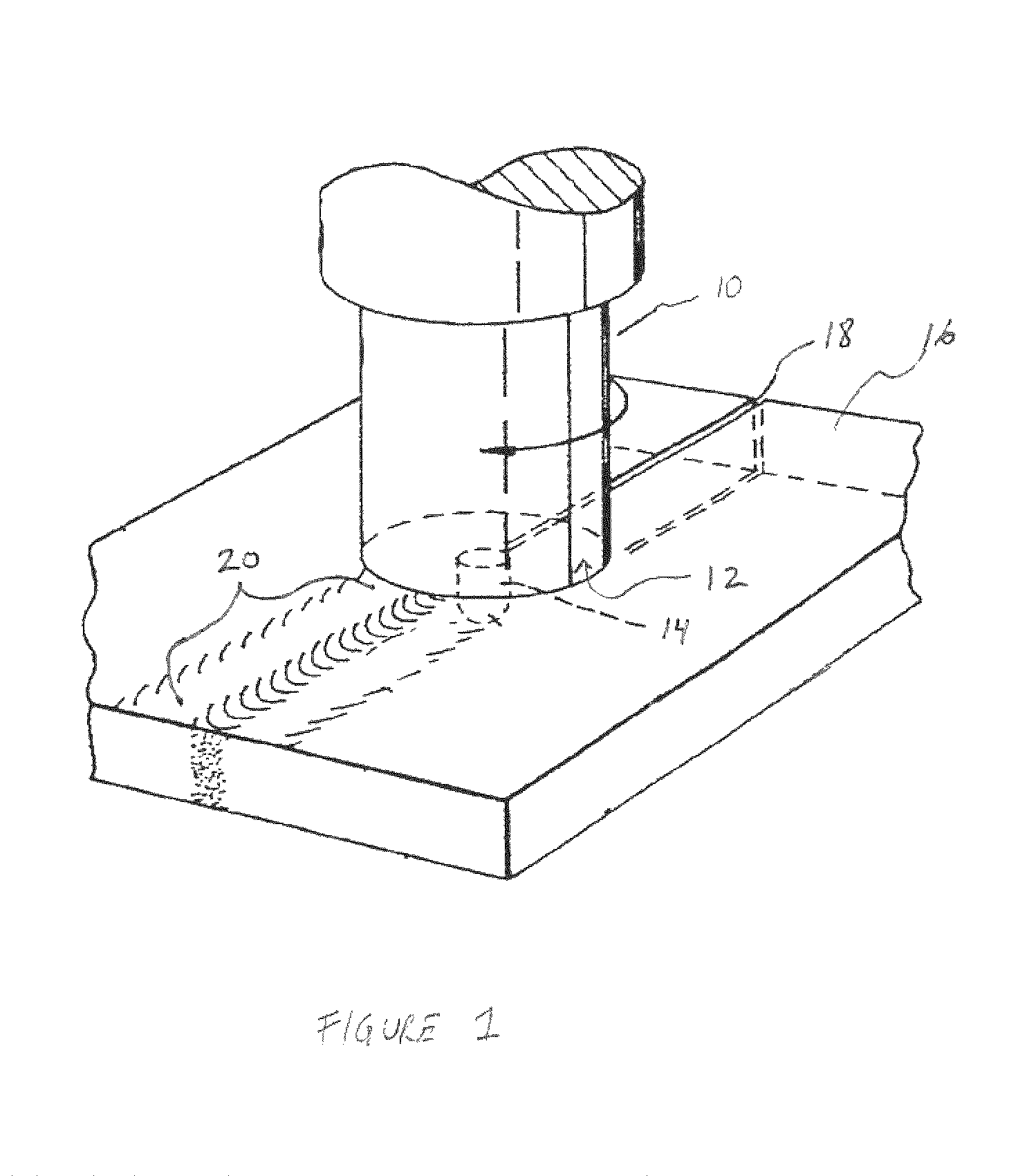
Joining pipe line is extremely costly because of the manpower and equipment needed to weld and move needed components. FIG. 3 shows the manpower and equipment needed to fusion weld a typical pipeline.
The difficulty with AHSS lies in the conventional fusion welding methods being used.
These defects are accepted because they cannot be eliminated even with sophisticated automated fusion welding systems.
Welding AHSS is far more difficult than existing pipe line steels because the material composition inherently causes more fusion welding defects.
While this mandrel 60 is an effective means to provide support on the opposite side of the tool, the hydraulics and controls are expensive and the construction of the pipe is therefore also costly.
This means that moving the mandrel requires additional equipment and support.
A further disadvantage is that this mandrel configuration must also have additional hydraulics and rams added to align two pipe segments, further adding to the weight of the mandrel 60.

Method used


Image

  • Expandable mandrel for use in friction stir welding
  • Expandable mandrel for use in friction stir welding
  • Expandable mandrel for use in friction stir welding

Examples


Embodiment Construction

[0039]Reference will now be made to the details of the invention in which the various elements of the present invention will be described and discussed so as to enable one skilled in the art to make and use the invention. It is to be understood that the following description is only exemplary of the principles of the present invention, and should not be viewed as narrowing the claims which follow.

[0040]The presently preferred embodiment of the invention is an expandable mandrel for use in friction stir welding operations on arcuate surfaces such as pipe. An expandable mandrel concept was developed that proved to be simple, light weight, and inexpensive. The construction of the mandrel is shown in the following steps.

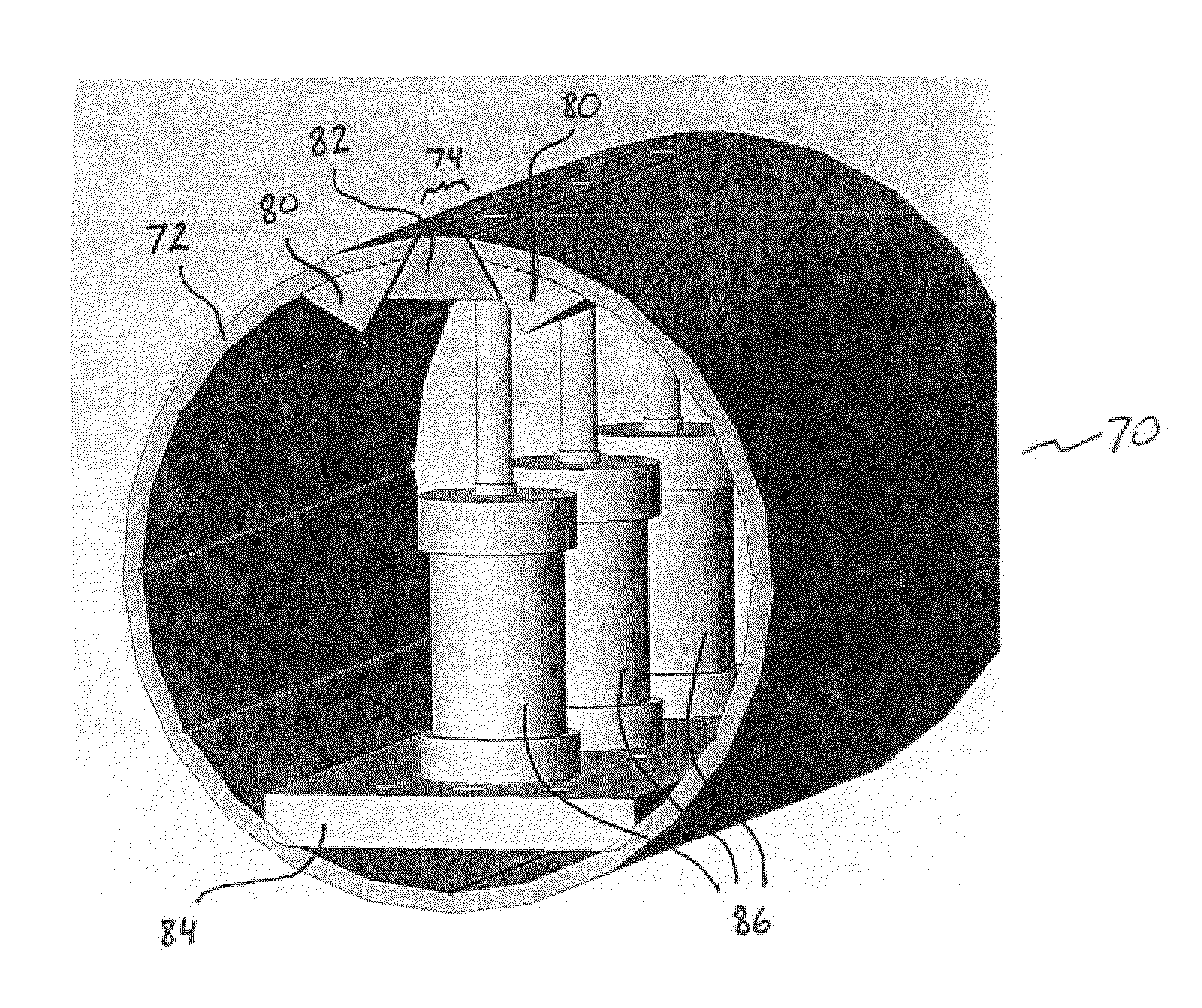
[0041]FIG. 6 shows a first embodiment of a mandrel shell 72 that forms an outer shell of the mandrel or “pipe pig”70 of the present invention. The mandrel shell 72 is a hollow cylinder having an opening or gap 74 along the length thereof. The diameter of the mandrel shel...


PUM

PropertyMeasurementUnit
diameteraaaaaaaaaa
outer diameteraaaaaaaaaa
inner diameteraaaaaaaaaa

Abstract

A mandrel that provides a counter-force to the pressure exerted on the outside of a pipe or other arcuate surface by a friction stir welding tool, wherein the mandrel is expandable through the use of a wedge, and wherein the mandrel enables multiple friction stir welding heads to simultaneously perform welding on the arcuate surface.

Description

BACKGROUND OF THE INVENTION[0001]1. Field of the Invention[0002]This invention relates generally to friction stir welding. More specifically, the present invention addresses improvements in the ability to perform friction stir welding of pipe or other arcuate objects, wherein a mandrel is needed to provide a counter-balancing force against the inside of the arcuate surface being welded, to thereby prevent a friction stir welding tool in contact with the outside of the arcuate surface from damaging the workpiece being welded.[0003]2. Description of Related Art[0004]Friction stir welding (hereinafter “FSW”) is a technology that has been developed for welding metals and metal alloys. The FSW process often involves engaging the material of two adjoining workpieces on either side of a joint by a rotating stir pin or spindle. Force is exerted to urge the spindle and the workpieces together and frictional heating caused by the interaction between the spindle and the workpieces results in p...

Claims


Application Information

Patent Timeline
Patent Type & Authority Patents(United States)
IPC IPC(8): B23K5/22B21B25/00
CPCB23K20/126B23K37/0531B23K2201/06B23K2101/06
Inventor PACKER, SCOTT M.BABB, JONATHAN A.STEEL, RUSSELL J.RUSSELL, MONTE
Owner MAZAK CORP
Learn More