
Ceramic and metal composite dental implant

a ceramic and metal composite technology, applied in dental implants, dental surgery, medical science, etc., can solve the problems of ceramic implants that have a history of breakage, implants are subjected to very high forces, and prosthetic teeth look unnatural and unhealthy, so as to achieve the initial stability of bone, promote gum tissue adhesion, and reduce the effect of the implant diameter

Inactive Publication Date: 2011-11-15
FOLSOM JR AUBREY C
View PDF18 Cites 33 Cited by
  • Summary
  • Abstract
  • Description
  • Claims
  • Application Information

AI Technical Summary

Benefits of technology

[0009]An advantage of the present invention is a ceramic dental implant that allows a portion of the ceramic implant to be placed in the gum tissue, promoting adherence of the gum tissue to the implant and allowing the gum tissue to retain its normal appearance.

Problems solved by technology

A problem with metal implants is that the coronal region of a metal implant shows through gum tissue as a dark shadow, thus making the prosthetic tooth look unnatural and unhealthy.
However, there are a number of problems associated with ceramic implants.
For example, dental implants are subjected to very high forces from mastication of food and, as a result, ceramic implants have a history of breakage due to their lack of tensile strength.
Further, ceramic implants are typically manufactured as one-piece constructs of the implant and the abutment and, as a result, these implants are difficult to restore if the angulations or location of the surgical placement deviate from ideal.
There are several disadvantages to this design.
If the ceramic sleeve is thin, it is fragile and the dark opaque metal of the implant shows through the gum making it appear less natural.
If the ceramic sleeve is made thicker to overcome the problems with the thin ceramic sleeve, the implant diameter becomes too large for the implant site.

Method used


Image

  • Ceramic and metal composite dental implant
  • Ceramic and metal composite dental implant
  • Ceramic and metal composite dental implant

Examples


Embodiment Construction

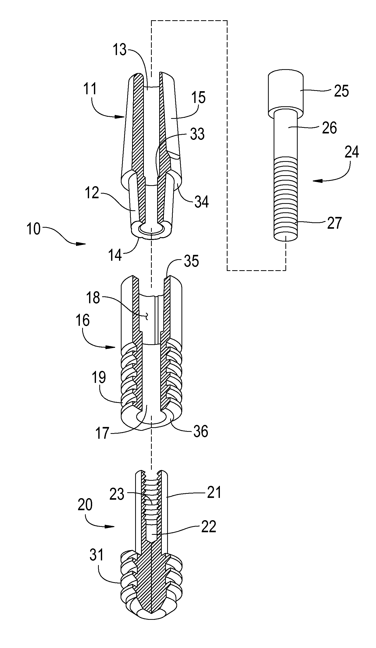
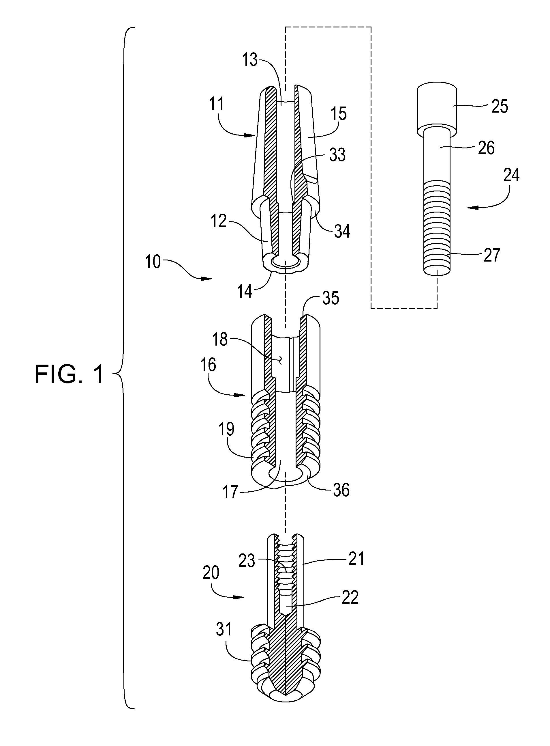
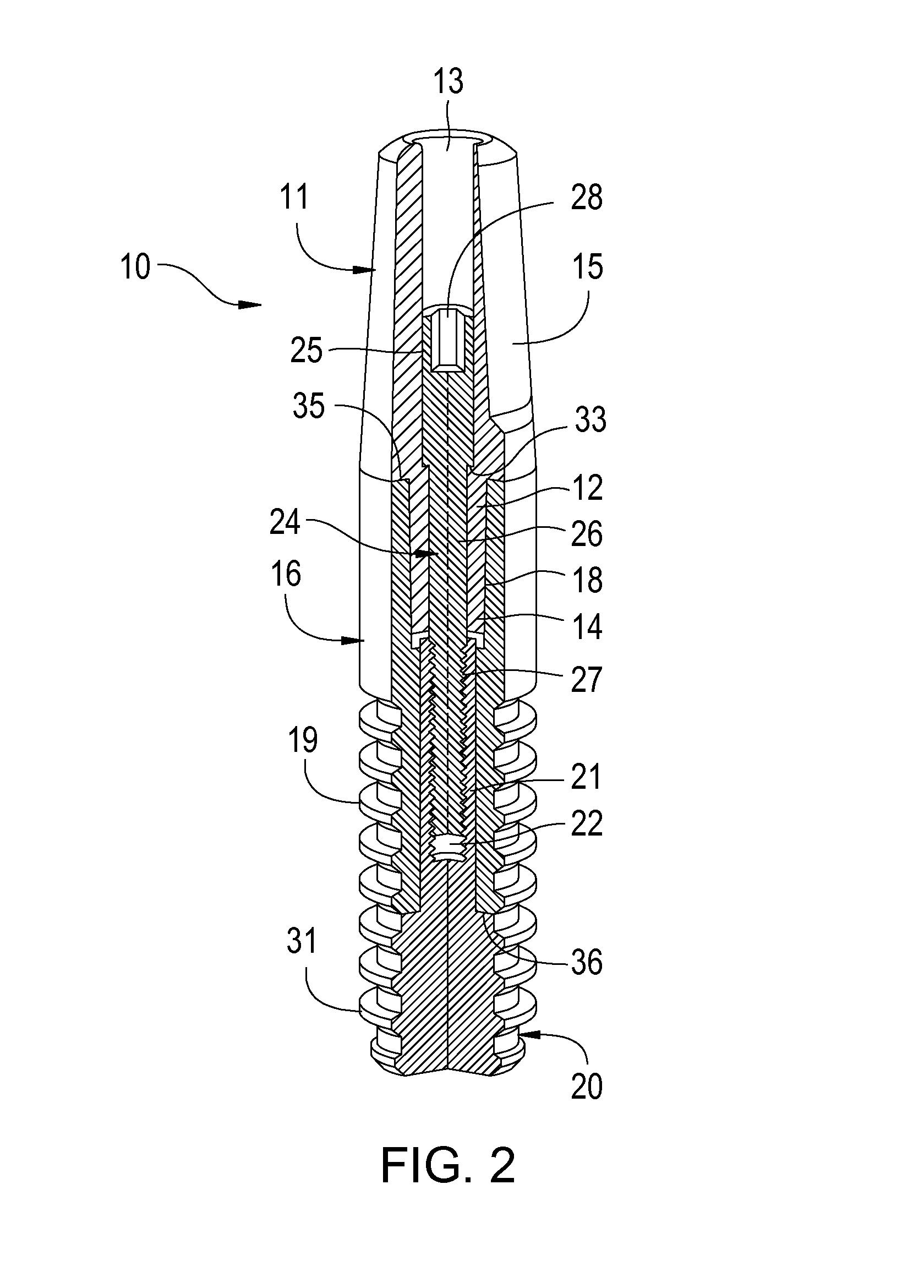
[0020]The preferred embodiment of the present invention is shown in FIGS. 1-3, wherein FIG. 1 is an exploded perspective view, partially in section, of the invention showing the components of the composite dental implant 10. An abutment 11 has a hollow interior 13, an exterior shelf 34, and an anti-rotational feature 12. The internal diameter of the anti-rotational feature 12 is slightly less than that of the abutment 11, producing an interior shelf 33. The anti-rotational feature 12 has convex protrusions 14 on its exterior surface. The abutment 11 may be made of ceramic or metal, such as titanium or gold.

[0021]The composite dental implant 10 has a hollow ceramic cylinder 16 having an interior cavity 17, a bottom (apical) end 36 and a top (coronal) end 35. The internal upper portion of hollow ceramic cylinder 16 has concave depressions 18 on its inner surface to engage the external convex protrusions 14 of the anti-rotational feature 12. Hollow ceramic cylinder 16 has external groo...


PUM

PropertyMeasurementUnit
diameteraaaaaaaaaa
diameteraaaaaaaaaa
diameteraaaaaaaaaa

Abstract

A dental implant having a hollow ceramic cylinder compressed between two metal components of the implant. A principal embodiment comprises a hollow ceramic cylinder, a hollow abutment with an anti-rotational feature, a metallic tip with a hollow metal core, and a screw. The metal core is press-fit into the ceramic cylinder providing a metallic tip at the apical or bottom end of the ceramic cylinder. The screw is inserted into the hollow abutment and extends into and screws into the metal core. By tightening the screw, the ceramic cylinder can be compressed to improve its strength, and the abutment is thereby reversibly attached to the hollow ceramic cylinder. The hollow ceramic cylinder is implantable in both bone and soft tissue, extends through the interface between the bone and soft tissue, maintains the normal appearance of gum tissue after implantation, and has a maximum diameter between 1.8 to 6 mm.

Description

FIELD OF THE INVENTION[0001]The present invention relates to tissue implants used to support prosthetic devices and, more particularly, to a dental implant comprising a compressed ceramic material to maintain the normal appearance of gum tissue and increase the tensile strength of the implant.BACKGROUND OF THE INVENTION[0002]Dental implants generally consist of an implant which is anchored within bone, and an abutment that is connected to the implant to support a prosthesis, such as a prosthetic tooth or denture. The abutment partially extends into the oral cavity in the position of the tooth it is to replace. The majority of dental implants are made of metal, usually titanium. Metal implants are easily threaded internally for attachment of prosthetic abutments. A problem with metal implants is that the coronal region of a metal implant shows through gum tissue as a dark shadow, thus making the prosthetic tooth look unnatural and unhealthy.[0003]Ceramic implants are light in color, ...

Claims


Application Information

Patent Timeline
Patent Type & Authority Patents(United States)
IPC IPC(8): A61C8/00
CPCA61C8/0012A61C8/0022
Inventor FOLSOM, JR., AUBREY C.
Owner FOLSOM JR AUBREY C
Learn More