Intervertebral disk prosthesis or artificial vertebral body

a technology of intervertebral disks and prostheses, which is applied in the field of prosthetic intervertebral disks or artificial vertebrae, can solve the problems of limited freedom of movement of the spinal column, low flexibility of the compression spring element, etc., and achieve the effect of low stiffness

Active Publication Date: 2011-11-15
SYNTHES USA
View PDF29 Cites 18 Cited by
  • Summary
  • Abstract
  • Description
  • Claims
  • Application Information

AI Technical Summary

Benefits of technology

[0007]sufficiently great elastic flexibility and damping in the case of low compressive forces; this ensures adequate freedom of mobility of the spinal column in this area;
[0022]In another embodiment, the cup springs have a stop which limits their compressibility. The stop protects the cup springs from overstressing. Therefore, higher forces can be absorbed without overloading the cup springs.

Problems solved by technology

One disadvantage of these known prosthetic intervertebral disks is the linear spring characteristic of the compression spring element, so that in the case of a compression spring element which should also absorb impact forces, the flexibility of the compression spring element is too low, in particular at low compressive forces.
Therefore the freedom of mobility of the spinal column is limited in this area.

Method used


Image

  • Intervertebral disk prosthesis or artificial vertebral body
  • Intervertebral disk prosthesis or artificial vertebral body
  • Intervertebral disk prosthesis or artificial vertebral body

Examples


Embodiment Construction

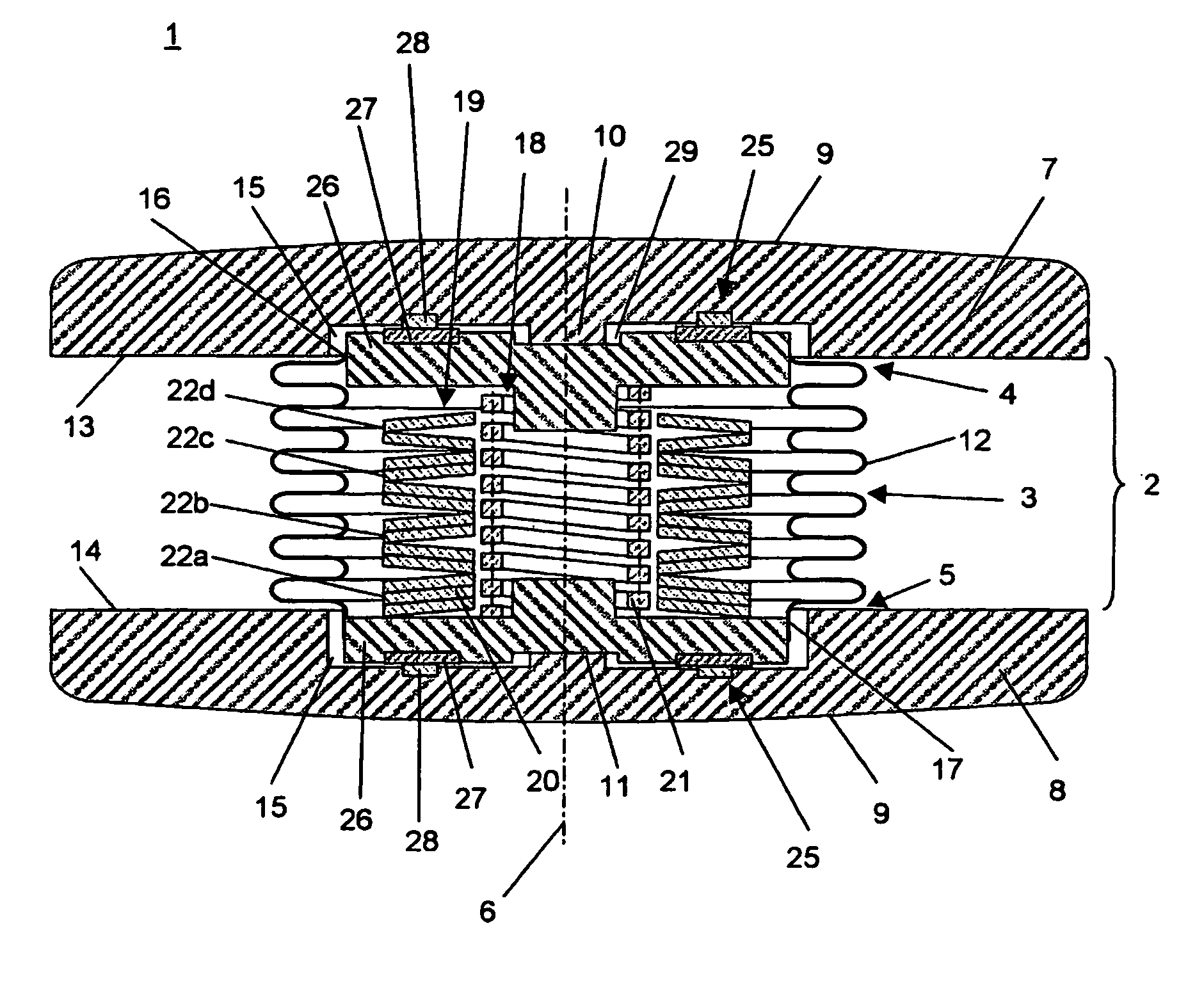
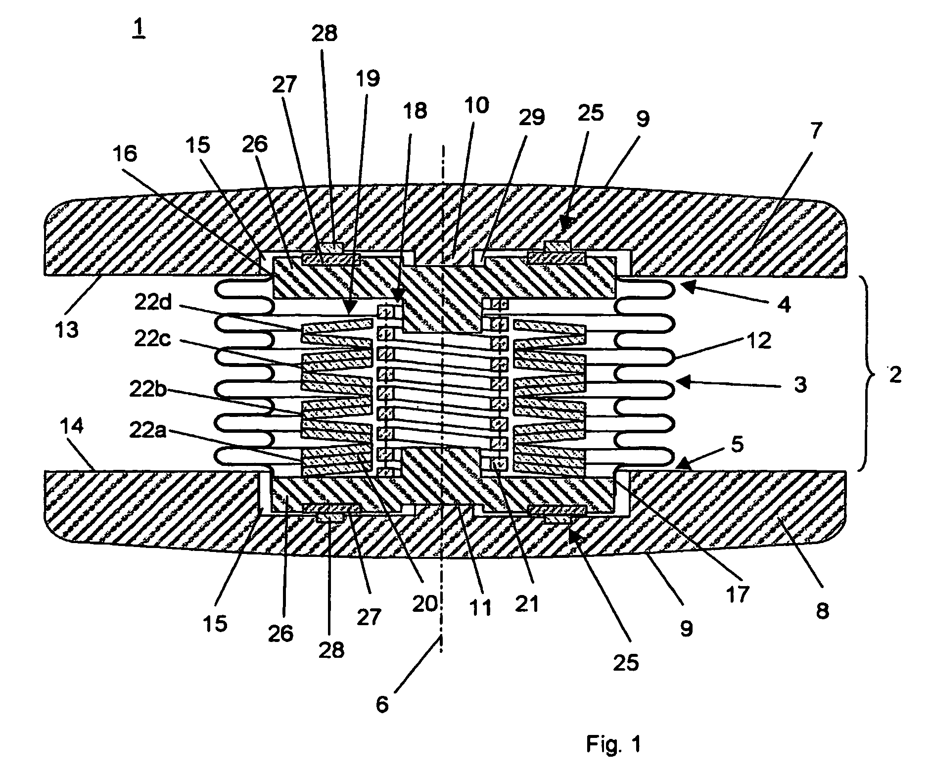
[0026]The embodiment of the prosthetic intervertebral disk 1 illustrated in FIG. 1 comprises a hollow cylindrical elastic middle part 2 having a jacket 3 designed as bellows 21, an upper end 4, a lower end 5, a central longitudinal axis 6, an upper apposition plate 7, and a lower apposition plate 8. Upper apposition plate 7 is arranged across longitudinal axis 6 at upper end 4 of middle part 2 and is suitable for coming in contact with the lower plate of a vertebra. Lower apposition plate 8 is arranged across longitudinal axis 6 at lower end 5 of middle part 2 and is suitable for coming in contact with the upper plate of a vertebra. The two apposition plates 7; 8 have a surface 9 with a convex curvature and axial pins 10 and 11 pointing inward. The jacket 3 in this embodiment includes bellows 12, which are attached to the two apposition plates 7; 8. Depending on the material, the bellows 12 may be welded, glued, or pressed to apposition plates 7; 8.

[0027]Upper apposition plate 7 has...


PUM


Abstract

An intervertebral disk prosthesis or the intervertebral implant has a cavity-like middle part with a longitudinal axis, an upper end, a lower end, an upper apposition plate, and a lower apposition plate. The upper apposition plate is placed on the upper end of the middle part such that it is perpendicular to the longitudinal axis. The upper apposition plate is suited for resting against the base plate of a vertebral body. The lower apposition plate is placed on the lower end of the middle part such that it is perpendicular to the longitudinal axis. The lower apposition plate is suited for resting against the cover plate of a vertebral body. The middle part has at least two coaxially arranged plate springs, which gives the middle part a progressive spring characteristic.

Description

CROSS-REFERENCE TO RELATED APPLICATION[0001]This is a continuation of pending International Application No. PCT / CH2004 / 000210, filed Apr. 2, 2004, the entire contents of which are expressly incorporated herein by reference thereto.FIELD OF THE INVENTION[0002]The invention relates to a prosthetic intervertebral disk or an artificial vertebral body.BACKGROUND OF THE INVENTION[0003]Intervertebral disks comprising two apposition plates with a compression spring element in between are known. A hollow cylindrical jacket is typically arranged around the compression spring element. The compression spring element is usually made of a memory metal alloy which has superelastic properties at body temperature, or in other embodiments, the compression spring element includes a cup spring column made up of cup springs having the same stiffness. One disadvantage of these known prosthetic intervertebral disks is the linear spring characteristic of the compression spring element, so that in the case ...

Claims


Application Information

Patent Timeline
Patent Type & Authority Patents(United States)
IPC IPC(8): A61F2/44A61F2/00A61F2/30
CPCA61F2/4425A61F2/30742A61F2002/30369A61F2002/30566A61F2002/30571A61F2002/443A61F2220/0033A61F2/44
Inventor STUDER, ARMINGAGO, MARIOTRACHSEL, JASON
Owner SYNTHES USA
Why Eureka
Try Eureka