Slidable choke microwave antenna

a microwave antenna and choke technology, applied in the field of microwave applicators, can solve the problems of inability to consistently maintain a predetermined impedance match between the microwave delivery system (e.g., generators, cables, etc., and the tissue surrounding the microwave antenna, and achieve the effect of effective delivery and dispersion of energy

Active Publication Date: 2011-11-15
TYCO HEALTHCARE GRP LP
View PDF204 Cites 101 Cited by
  • Summary
  • Abstract
  • Description
  • Claims
  • Application Information

AI Technical Summary

Problems solved by technology

Conventional microwave antennas tend to have a narrow operational bandwidth, a wavelength range at which optimal operational efficiency is achieved, and hence, are incapable of consistently maintaining a predetermined impedance match between the microwave delivery system (e.g., generator, cable, etc.) and the tissue surrounding the microwave antenna.
As a result, there is a mismatch between the bandwidth of conventional microwave antenna and the microwave energy being applied.
Thus, narrow band microwave antennas tend to detune over use hindering the effective delivery and dispersion of energy.
However, these improvements tend to compromise the structural integrity of the antennas, requiring additional enhancement and / or instrumentation instruments to facilitate insertion of the antenna intro the target treatment area.

Method used


Image

  • Slidable choke microwave antenna
  • Slidable choke microwave antenna
  • Slidable choke microwave antenna

Examples


Embodiment Construction

[0023]Particular embodiments of the present disclosure will be described herein below with reference to the accompanying drawings. In the following description, well-known functions or constructions are not described in detail to avoid obscuring the present disclosure in unnecessary detail.

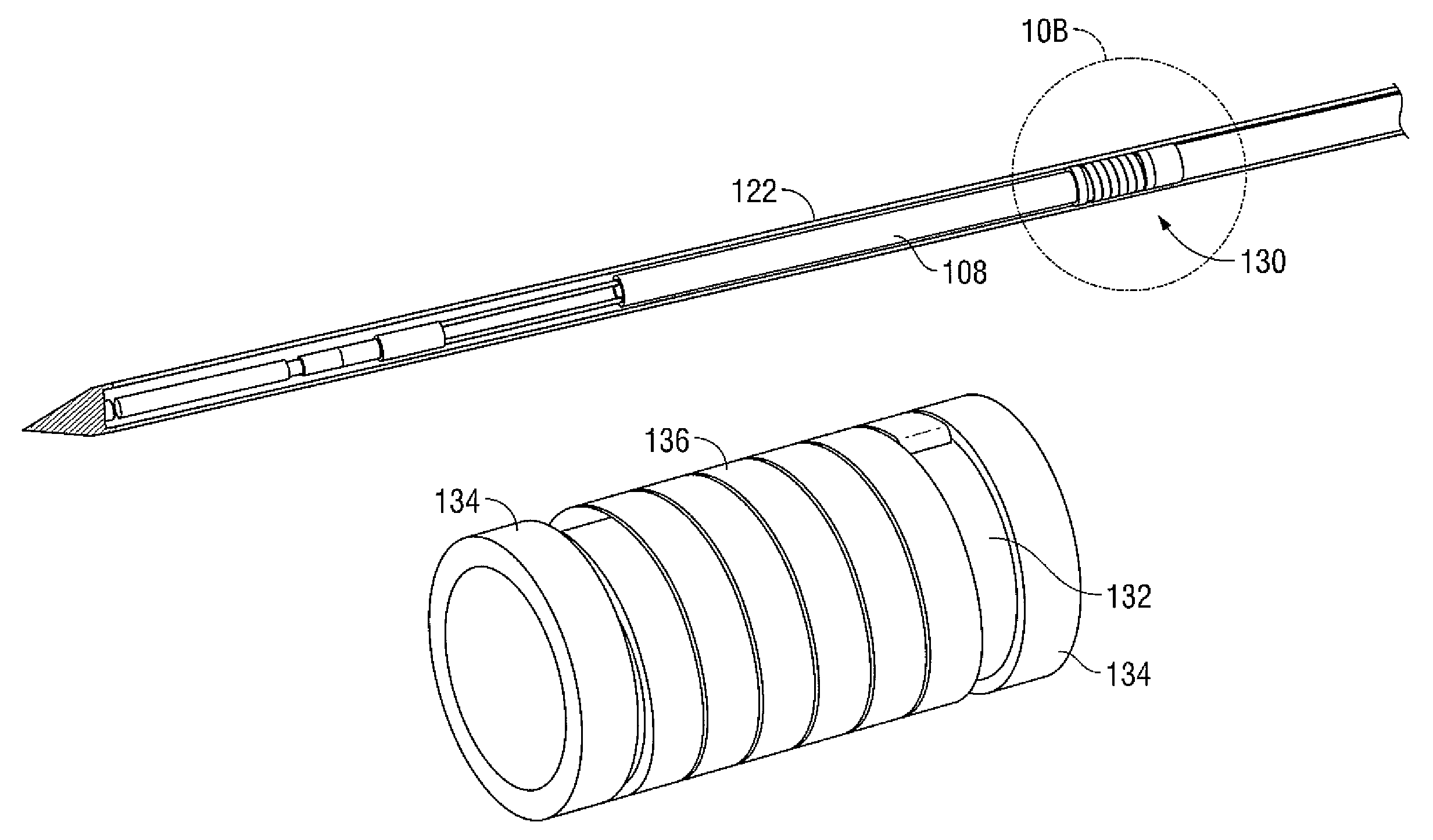
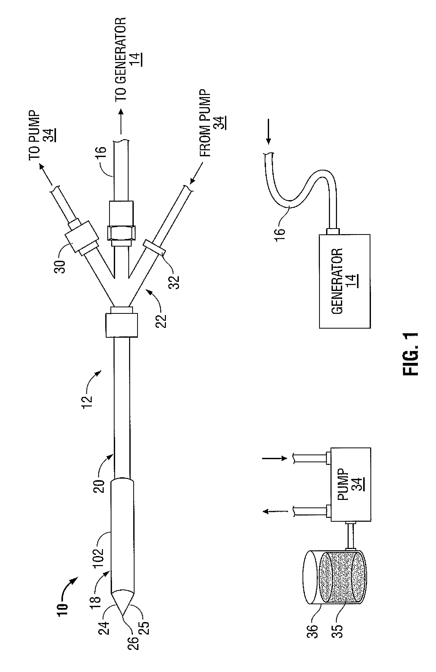
[0024]FIG. 1 shows a microwave ablation system 10 that includes a microwave antenna assembly 12 coupled to a microwave generator 14 via a flexible coaxial cable 16. In one embodiment, the generator 14 is configured to provide microwave energy at an operational frequency from about 500 MHz to about 5000 MHz.

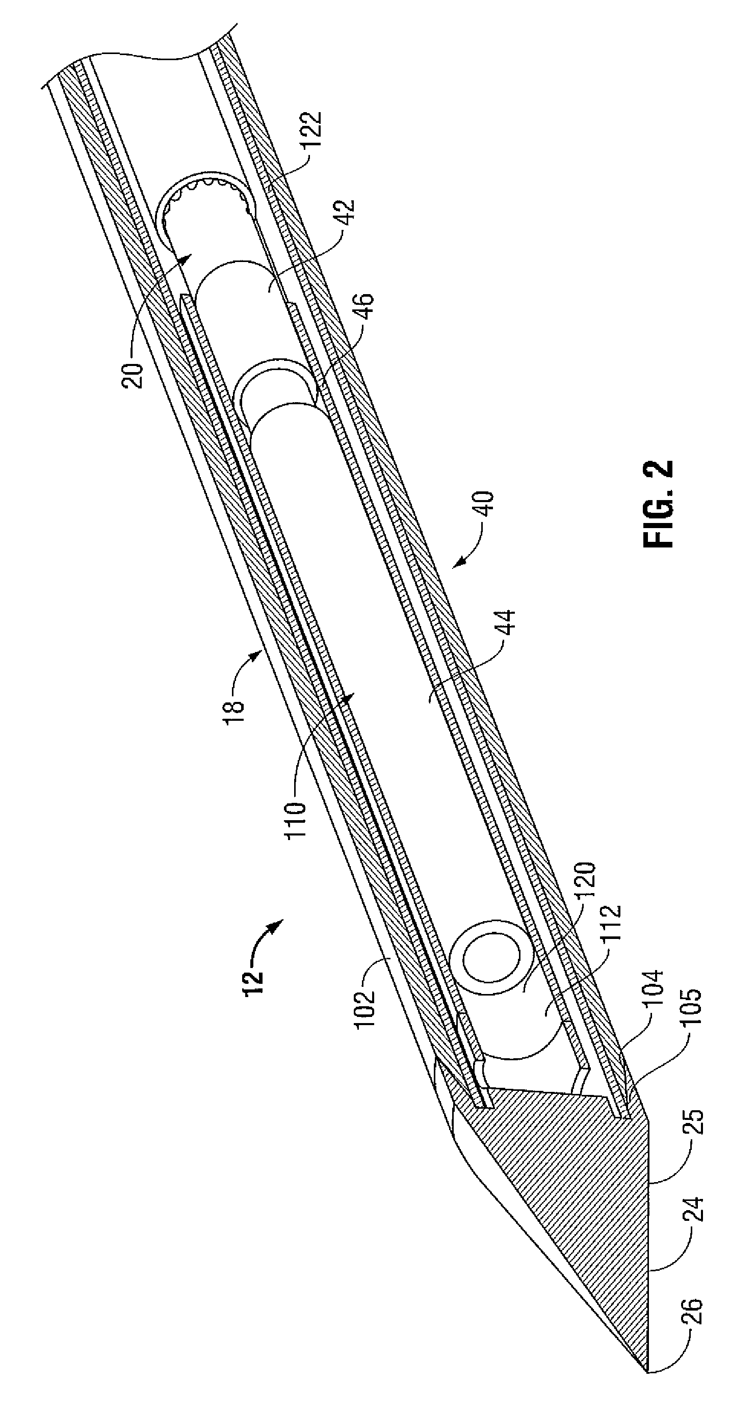
[0025]The antenna assembly 12 includes a radiating portion 18 that is connected by a feedline 20 (or shaft) to the cable 16. More specifically, the antenna assembly 12 is coupled to the cable 16 through a connection hub 22. The connection hub 22 also includes an outlet fluid port 30 and an inlet fluid port 32 defined therein that are in fluid communication with the radiating portion 18 and the f...


PUM


Abstract

A microwave antenna assembly is disclosed. The antenna assembly includes a feedline having an inner conductor, an outer conductor and an inner insulator disposed therebetween and a radiating portion including a dipole antenna coupled to the feedline and a trocar coupled to the dipole antenna at a distal end thereof. The antenna assembly also includes a slidable outer jacket disposed about the radiating portion and the feedline. The slidable outer jacket being configured to slide about at least one of the radiating portion and the feedline from a closed configuration, in which the slidable outer jacket is mated with the trocar and a retracted configuration, in which the slidable outer jacket is retracted in a proximally exposing at least a portion the radiating portion.

Description

BACKGROUND[0001]1. Technical Field[0002]The present disclosure relates generally to microwave applicators used in tissue ablation procedures. More particularly, the present disclosure is directed to a microwave applicator having a slidable jacket that acts an electrical termination choke.[0003]2. Background of Related Art[0004]Treatment of certain diseases requires destruction of malignant tissue growths (e.g., tumors). It is known that tumor cells denature at elevated temperatures that are slightly lower than temperatures injurious to surrounding healthy cells. Therefore, known treatment methods, such as hyperthermia therapy, heat tumor cells to temperatures above 41° C., while maintaining adjacent healthy cells at lower temperatures to avoid irreversible cell damage. Such methods involve applying electromagnetic radiation to heat tissue and include ablation and coagulation of tissue. In particular, microwave energy is used to coagulate and / or ablate tissue to denature or kill the ...

Claims


Application Information

Patent Timeline
Patent Type & Authority Patents(United States)
IPC IPC(8): A61B18/18H01Q1/42H01Q9/04
CPCA61B18/18H01Q9/16A61B18/1815A61B2018/00023
Inventor BONN, KENLYN
Owner TYCO HEALTHCARE GRP LP
Why Eureka
Try Eureka