Moving picture processing method
a processing method and moving picture technology, applied in the field of moving picture processing method, can solve the problems of losing patterns in some cases, and achieve the effects of enhancing the subjective image quality perceived by viewers, reducing the amount of processing load as well as the size of the circuit, and high practical valu
- Summary
- Abstract
- Description
- Claims
- Application Information
AI Technical Summary
Benefits of technology
Problems solved by technology
Method used
Image
Examples
first embodiment
[0072]The following describes the moving picture processing apparatus according to the first embodiment of the present invention.
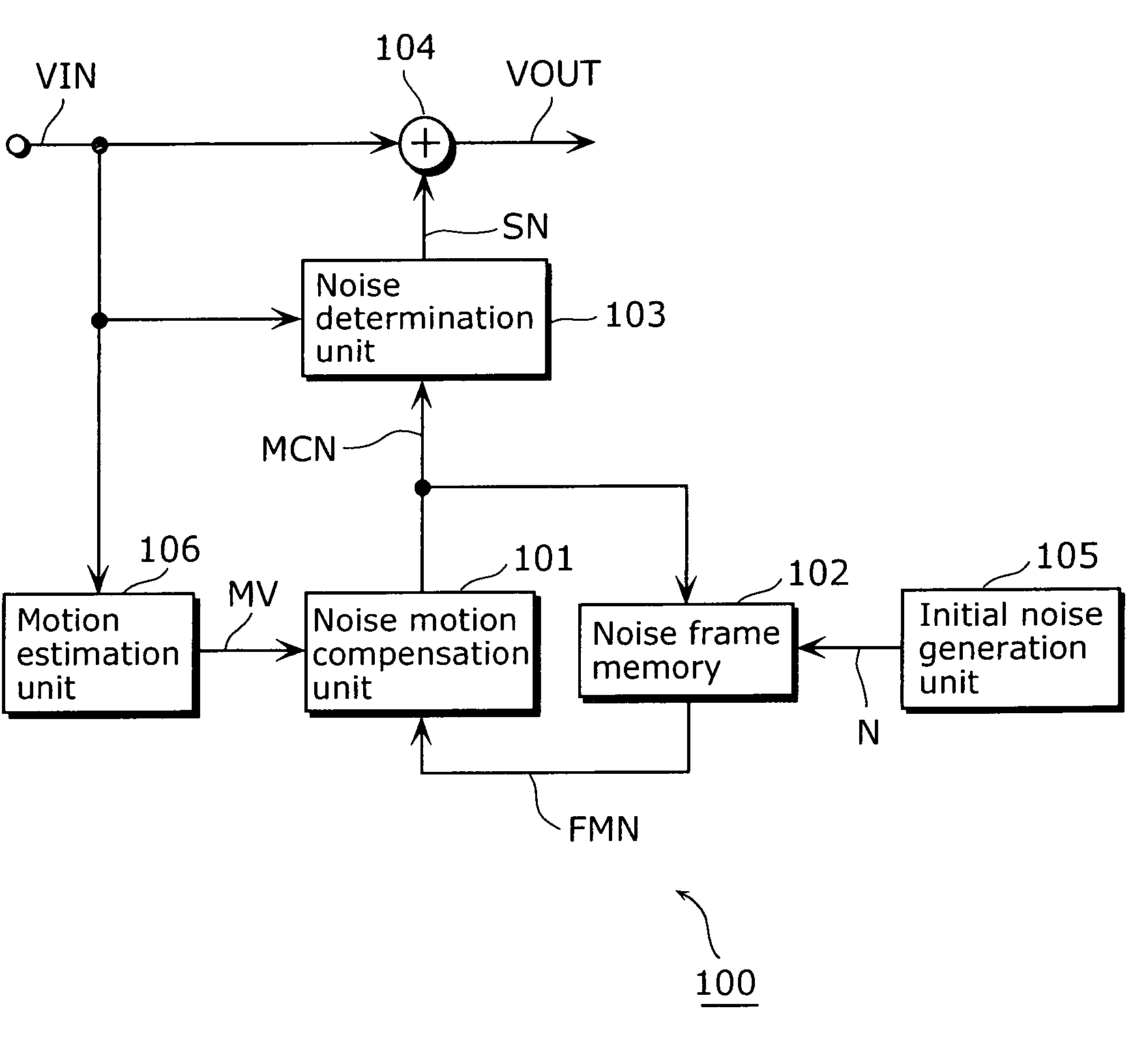
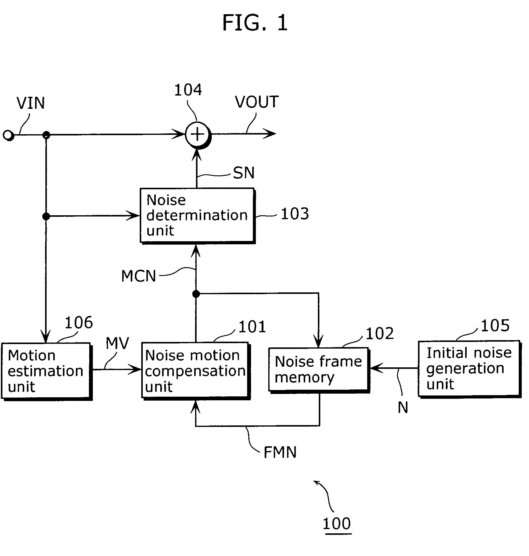
[0073]FIG. 1 is a block diagram showing the moving picture processing apparatus according to the embodiment.
[0074]A moving picture processing apparatus 100 of the embodiment shifts noise according to a movement of an image indicated by an input image signal VIN, so as to superimpose the noise on the image. The moving picture processing apparatus 100 includes a noise motion compensation unit 101, a noise frame memory 102, a noise determination unit 103, an adder 104, an initial noise generation unit 105 and a motion estimation unit 106.
[0075]The initial noise generation unit 105 generates a noise signal N for superimposing noise on the input image signal VIN and outputs the noise signal N to the noise frame memory 102. The noise signal N is, for example, a noise signal which indicates previously-specified random noise. Also, the noise in the embodiment is a...
second embodiment
[0127]The moving picture processing apparatus according to the second embodiment of the present invention decodes a coded picture signal BS indicating coded pictures, and superimposes noise onto the decoded pictures through the same processing as described in the first embodiment.
[0128]FIG. 7 is a block diagram showing the moving picture processing apparatus according to the embodiment.
[0129]A moving picture processing apparatus 200 of the embodiment includes a decoding processing unit 110, an image motion compensation unit 111, a picture frame memory 112, an adder 113, the adder 104, the noise determination unit 103, the noise frame memory 102, the initial noise generation unit 105 and the noise motion compensation unit 101. That is to say that the moving picture processing apparatus 200 includes the components of the moving picture apparatus 100 of the first embodiment, except for the motion estimation unit 106, and further includes the decoding processing unit 110, the image moti...
third embodiment
[0155]When a coded picture signal is generated by coding a moving picture with the picture coding apparatus according to the third embodiment, the coded picture signal includes a noise flag indicating whether or not to superimpose noise on a decoded moving picture, and a motion compensation flag indicating whether or not to generate noise through motion compensation.
[0156]FIG. 10 is a block diagram showing a picture coding apparatus 300 according to the embodiment.
[0157]The picture coding apparatus 300 includes a moving picture coding unit 301, an image judgment unit 302, a supplementary information coding unit 303 and an adder 304.
[0158]The moving picture coding unit 301 generates a coded picture signal BS by performing compressive coding on each picture indicated by an input image signal VIN, and outputs the coded image signal BS. In addition, the moving picture coding unit 301 decodes each of the coded pictures and outputs a decoded image signal LDV indicating the decoded picture...
PUM
 Abstract
Description
Claims
Application Information
 - R&D
- Intellectual Property
- Life Sciences
- Materials
- Tech Scout
- Unparalleled Data Quality
- Higher Quality Content
- 60% Fewer Hallucinations
Browse by: Latest US Patents, China's latest patents, Technical Efficacy Thesaurus, Application Domain, Technology Topic, Popular Technical Reports.
© 2025 PatSnap. All rights reserved.Legal|Privacy policy|Modern Slavery Act Transparency Statement|Sitemap|About US| Contact US: help@patsnap.com


