Method of manufacturing stator core of electric rotating machine

a technology of electric rotating machines and stator cores, which is applied in the direction of magnets, electromagnets, magnetic bodies, etc., can solve the problems of lowering the level of electric power, lowering the mechanical strength of steel sheets, and increasing the iron loss in the core caused by the operation of the alternator, so as to increase the effect of heightening the resistance to the ironing load

Inactive Publication Date: 2011-11-22
DENSO CORP
View PDF6 Cites 2 Cited by
  • Summary
  • Abstract
  • Description
  • Claims
  • Application Information

AI Technical Summary

Benefits of technology

[0021]An object of the present invention is to provide, with due consideration to the drawbacks of the conventional stator core manufacturing method, a method of manufacturing a stator core of an electric rotating machine wherein ironing is performed for steel sheets of the stator core to precisely adjust the outer diameter of the stator core while preventing the formation of any inter-sheet opening.
[0023]Because the thinned outer end portions of the steel sheets are brought into contact with one another, each thinned outer end portion heightens the resistance to the ironing load directed in the axial direction and is hardly deformed, bent or buckled toward the axial direction. Therefore, when the ironing load is given to each thinned outer end portion, no inter-sheet opening is formed between the thinned outer end portions, but plastic deformation directed toward the radial direction is easily caused in the thinned outer end portion. This plastic deformation is uniformly distributed along the circumferential direction of the laminated core. Therefore, in response to the ironing load, each thinned outer end portion is uniformly set back along the circumferential direction.
[0024]Accordingly, when each thinned outer end portion is set back along the circumferential direction in response to the ironing load, the length of the thinned outer end portion in the radial direction can be uniformly shortened along the circumferential direction, the length of the thinned outer end portion can be uniformly shortened along the circumferential direction, and the lengths of the thinned outer end portions can be precisely shortened at the predetermined value. That is, the outer diameter of the stator core can be precisely adjusted.
[0025]Further, because each thinned outer end portion heightens the resistance to the ironing load directed in the axial direction, this method can prevent any inter-sheet opening from being formed between the thinned outer end portions.

Problems solved by technology

In this case, iron loss in the core caused during the operation of the alternator is undesirably increased.
When the cycle of the magnetic field is reduced by lowering the rotation speed of the alternator, the level of the electric power is undesirably lowered.
However, when the steel sheet is thinned, the mechanical strength of the steel sheet is lowered.
This large opening (hereinafter, called inter-sheet opening) is not good in view of the external appearance of the stator core.
Regarding the quality of the stator core, the stator core is easily rusted at the bent portion forming the inter-sheet opening.
Regarding the performance of the stator core, the inter-sheet opening increases the magnetic resistance of the stator core so as to lower the strength of the magnetic field, and electric power outputted from an alternator using this stator core is undesirably lowered.
Therefore, it is difficult to reliably hold the steel sheets in the alternator.
Moreover, as described above, the steel sheets of the stator core have been thinned to reduce the iron loss caused in the core, so that the rigidity or mechanical strength of the steel sheets along the axial direction is inevitably lowered.

Method used


Image

  • Method of manufacturing stator core of electric rotating machine
  • Method of manufacturing stator core of electric rotating machine
  • Method of manufacturing stator core of electric rotating machine

Examples


embodiment 1

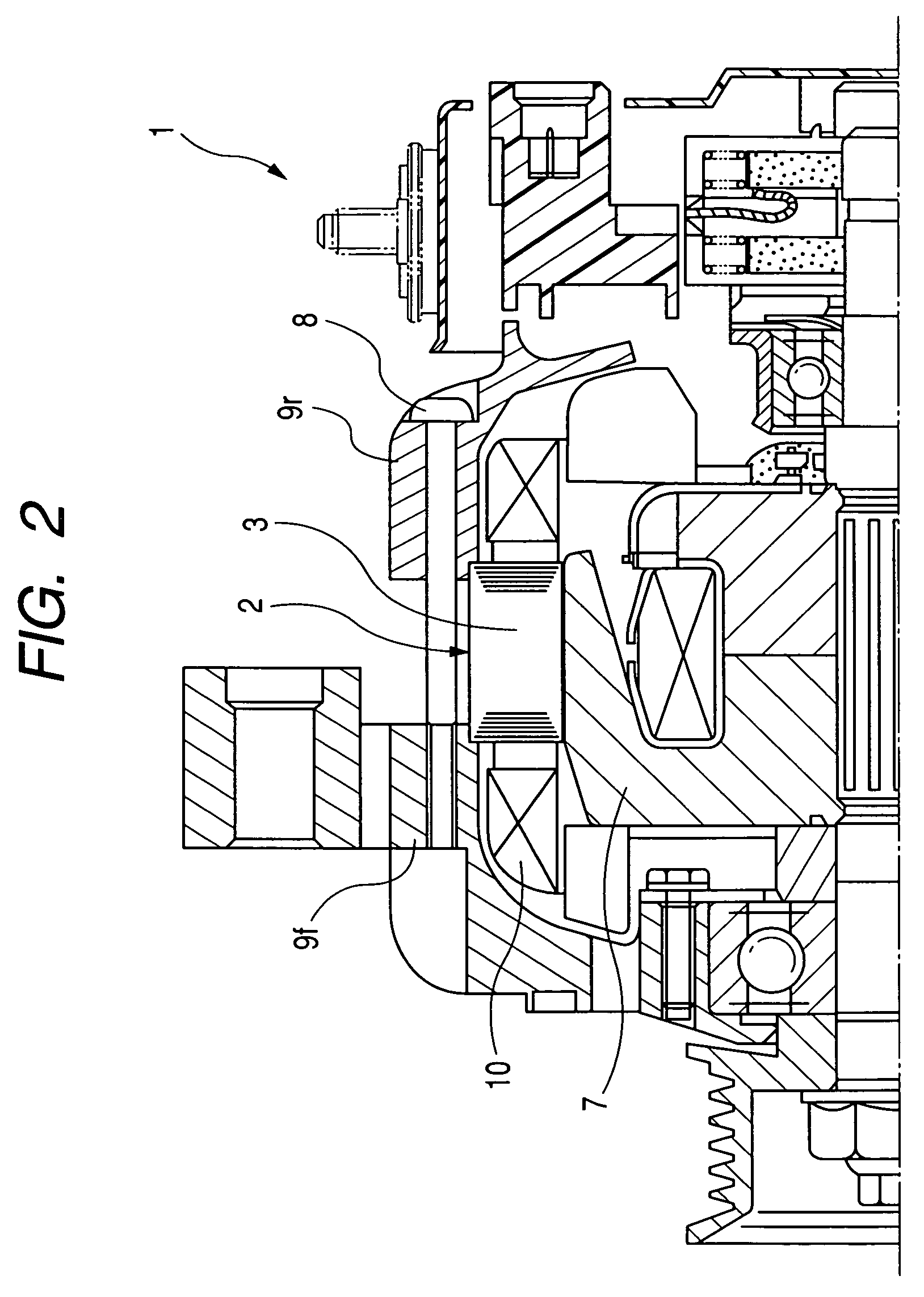
[0040]A method of manufacturing a stator core of an alternator representing an electric rotating machine mounted in a vehicle will be described. FIG. 2 is a side view, partially in cross-section, of an upper half portion of an alternator with a stator core.

[0041]As shown in FIG. 2, an alternator 1 has a cylindrical stator 2, a columnar rotor 7 disposed in a center hole of the stator 2, a front frame 9f covering the stator 2 and the rotor 7 on the front side of the alternator 1, a rear frame 9r covering the stator 2 and the rotor 7 on the rear side of the alternator 1, and a plurality of through bolts 8 fastening the stator 2 to the frames 9f and 9r. The stator 2 has a cylindrical stator core 3 and a plurality of stator coils 10 wound on the core 3. The core 3 is fixed to the frames 9f and 9r by the through bolts 8. The rotor 7 acts as a field. The stator 2 acts as an armature.

[0042]With this structure of the alternator 1, when the rotor 7 is rotated on its own axis in response to an...

embodiment 2

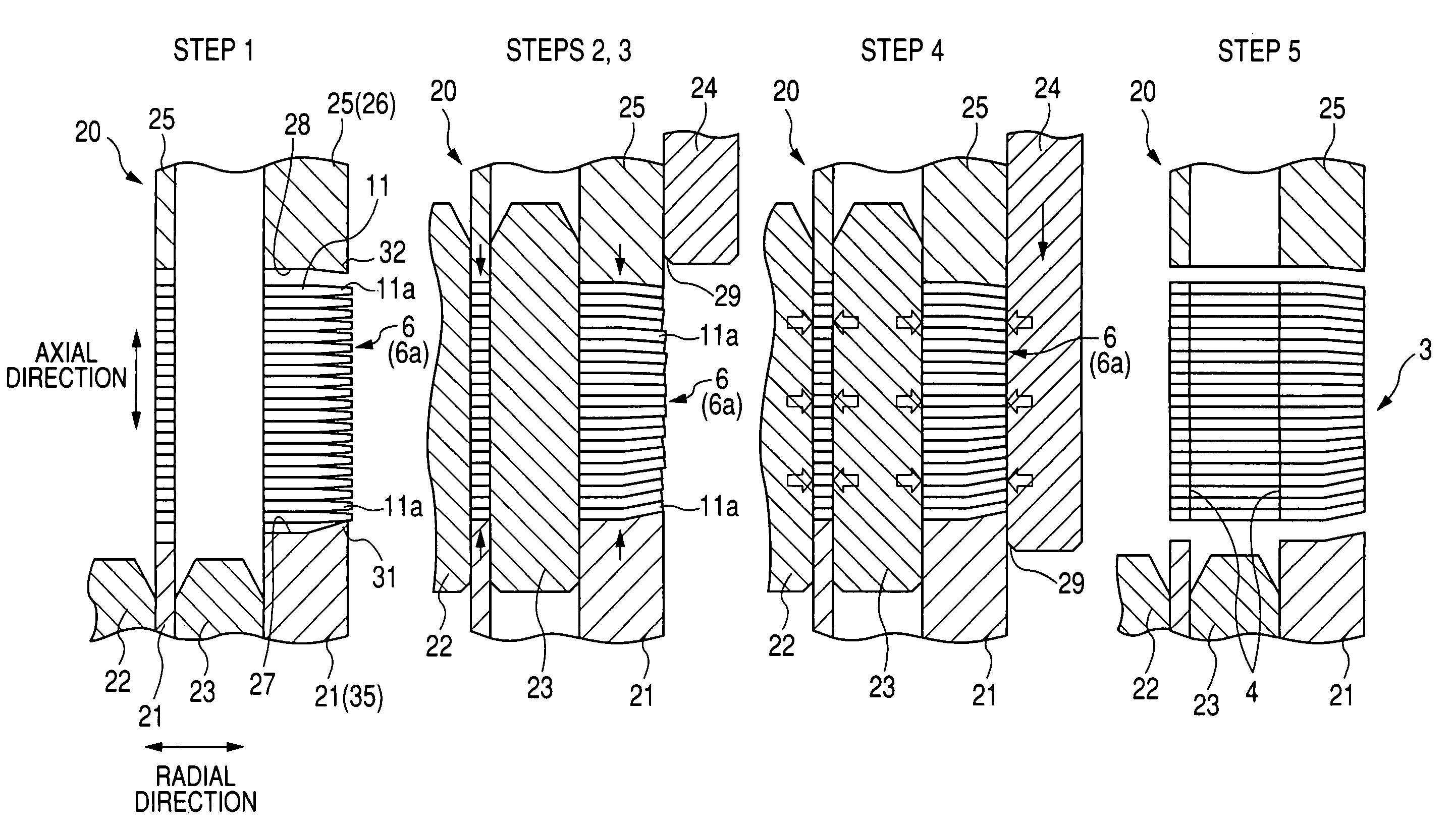
[0103]In the first embodiment, as shown in FIG. 6, when the member 25 presses the core 6 on the member 21, the outer end portions of the core 6 are bent along the shapes of the protrusions 31 and 32. In this case, the outer end portions placed at the axial ends of the core 6 are largely bent, but the outer end portions placed in the center of the core 6 are slightly bent. Therefore, when the core 6 is manufactured so as to have the sheets 11 approximately set at the same outer diameter, the margin for ironing (i.e., length of the outer end portion protruded from the members 21 and 25 in the radial direction) is large in the center of the core 6 but is small at the axial ends of the core 6. To uniformly and reliably shorten the outer end portions at a predetermined value, the core 6 is manufactured such that the margin for ironing is appropriately large at any position of the core 6 in the axial direction.

[0104]In contrast, in the second embodiment, the ironing member 24 is modified....


PUM

PropertyMeasurementUnit
shapeaaaaaaaaaa
lengthsaaaaaaaaaa
lengthaaaaaaaaaa

Abstract

In a method of manufacturing a stator core of an electric rotating machine, a cylindrical laminated core is formed by thinning a side portion of a steel plate with magnetic pole teeth and helically winding the steel sheet, and the stator core is manufactured by performing ironing for the laminated core. This laminated core has steel sheets aligned along the axial direction thereof, and the sheets have respective thinned outer end portions spaced apart from one another on the outer side of the laminated core. In the ironing, the thinned outer end portions of the steel sheets are brought into contact with one another in a forming apparatus, and an ironing load is given to the thinned outer end portions to shorten lengths of the thinned outer end portions in the radial direction of the laminated core at a predetermined value.

Description

CROSS-REFERENCE TO RELATED APPLICATION[0001]This application is based upon and claims the benefit of priority of the prior Japanese Patent Application 2007-244803 filed on Sep. 21, 2007, so that the contents of which are incorporated herein by reference.BACKGROUND OF THE INVENTION[0002]1. Field of the Invention[0003]The present invention relates to a method of manufacturing a stator core of an electric rotating machine by thinning outer end portions of steel sheets of the core and performing ironing for the outer end portions.[0004]2. Description of Related Art[0005]A small-sized electric rotating machine efficiently generating a rotational force or electric power has been recently desired. In an alternator representing the machine, a stator core formed of a lamination of steel sheets is disposed, and a conductor is wound on the stator core so as to be received in slots of the core and to be protruded from both ends of the slots as coil ends. To manufacture a small-sized alternator ...

Claims


Application Information

Patent Timeline
Patent Type & Authority Patents(United States)
IPC IPC(8): H02K15/00
CPCB21D11/085B21D35/00H02K15/026Y10T29/49009Y10T29/49071
Inventor TOKIZAWA, TAKASHI
Owner DENSO CORP
Why Eureka
Try Eureka