Heat exchanger block

Active Publication Date: 2011-11-22
MODINE MFG CO
View PDF79 Cites 21 Cited by
  • Summary
  • Abstract
  • Description
  • Claims
  • Application Information

AI Technical Summary

Benefits of technology

[0012]In yet another form of this aspect of the invention, an intermediate insert is b

Problems solved by technology

However, such connections can be difficult in a variety of applications, for example when the heat exchanger block consists of heat exchangers which are different in size, configuration and/or purpose.
While this may be advantageously used with heat exchanger blocks in which the heat exchangers do not vary in size, it also poses problems when the heat exchanger block is to be assembled from heat exchangers of different sizes.
Further, the heat exchangers in DE 195

Method used


Image

  • Heat exchanger block
  • Heat exchanger block
  • Heat exchanger block

Examples


Embodiment Construction

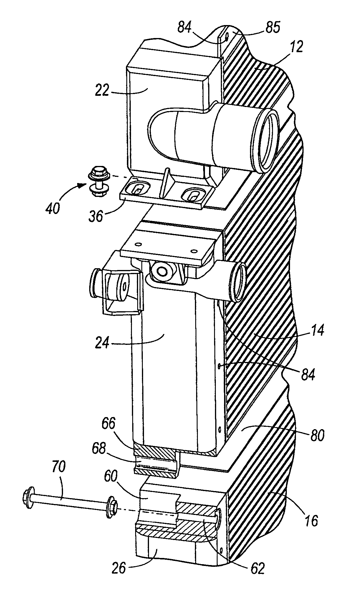
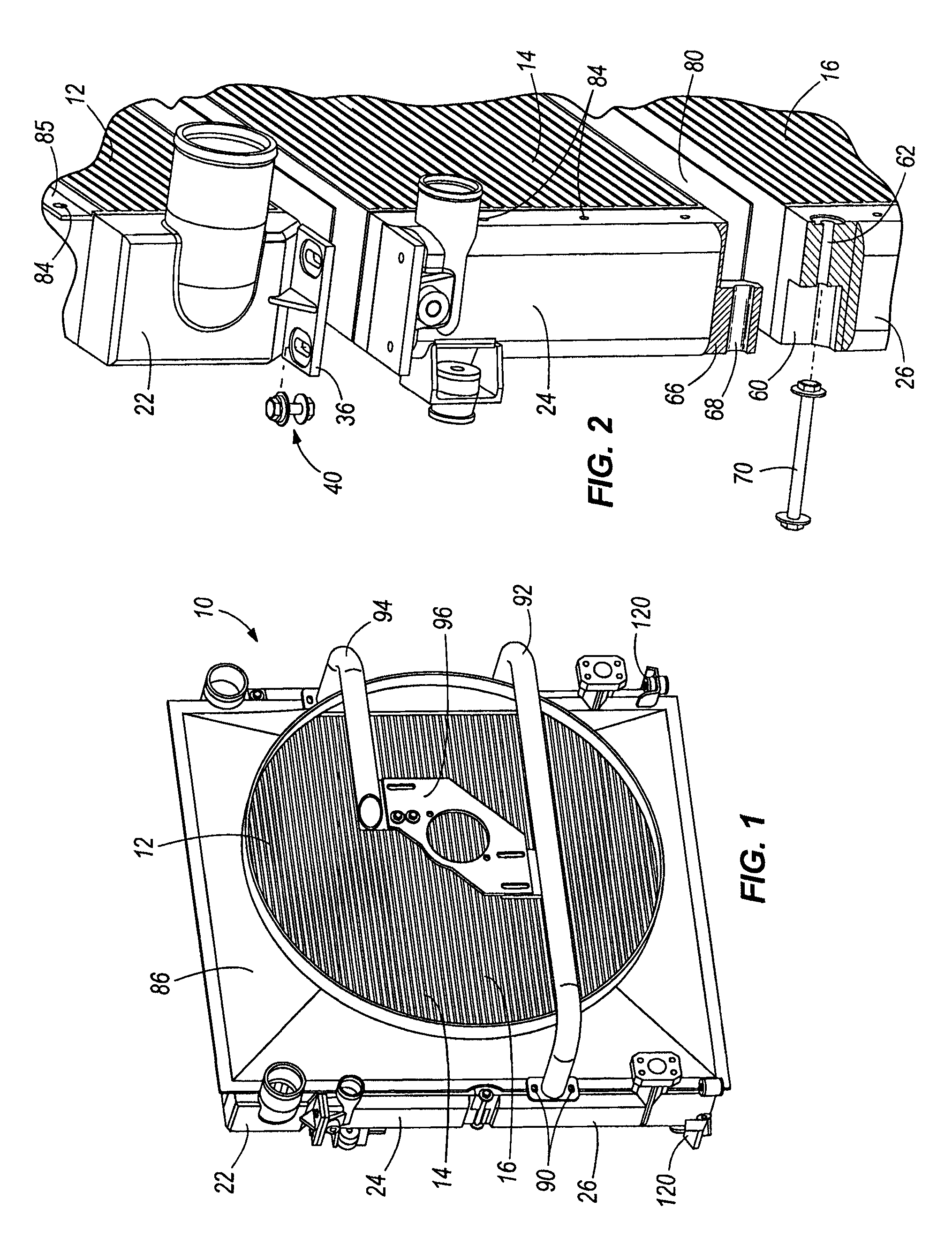
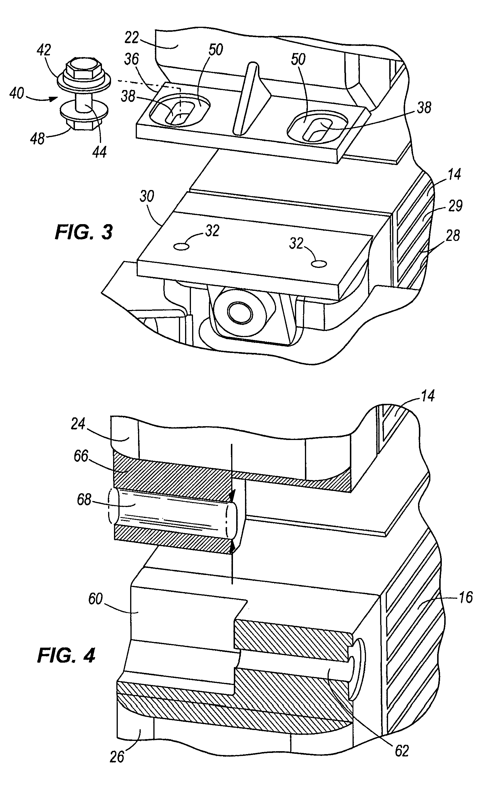
[0032]The Figures illustrate a heat exchanger block 10 according to the present invention. The heat exchanger block 10 may be advantageously used, for example, with vehicles in the off-highway sector (e.g., with a construction machine or agricultural machine). In accordance with the invention, the block 10 may consist of a plurality of separate heat exchangers, such as the illustrated three heat exchangers 12, 14, 16. As further described below, the heat exchangers 12, 14, 16 are secured with their collecting tanks or headers 22, 24, 26 in alignment with one another. The heat exchangers 12, 14, 16 may have different depths, in which case one side (e.g., the rear face relative to the direction of travel when used in a vehicle) may be aligned in generally the same (vertical) plane, with the other side (e.g., the front face) adapted to for equalization.

[0033]The heat exchangers 12, 14, 16 may each be configured in any suitable, desired manner according to the heat exchanging requiremen...


PUM


Abstract

A heat exchanger block including at least two heat exchangers each including a pair of longitudinal headers with tubes extending between the headers, at least some of which are aluminum cast parts. Adjacent heat exchangers are detachably connected at adjacent ends of their headers wherein one of the adjacent headers includes a recessed portion in the adjacent end and the other of the adjacent headers includes a flange receivable in the recess of the one header. Matching holes extend through the flange and the one header end, and a fastener extends through the matching holes in the ends of at least one set of adjacent headers. Shroud attachments are along a longitudinal wall of at least one of the longitudinal headers.

Description

CROSS REFERENCE TO RELATED APPLICATION(S)[0001]Not applicable.STATEMENT REGARDING FEDERALLY SPONSORED RESEARCH OR DEVELOPMENT[0002]Not applicable.REFERENCE TO A MICROFICHE APPENDIX[0003]Not applicable.TECHNICAL FIELD[0004]The present invention relates to heat exchangers, and more particularly to heat exchanger blocks having a plurality of heat exchangers connected together.BACKGROUND OF THE INVENTION AND TECHNICAL PROBLEMS POSED BY THE PRIOR ART[0005]Heat exchanger blocks are known, for example, from European Patent Application 0 515 924 A, in which multiple heat exchangers are screwed to each other in a manner not further shown, with the collecting tank or header for the coolant cooler integrated in the collecting tank or header for the oil cooler. Detachably assembled heat exchanger blocks are advantageous because detachable connection of the heat exchangers can be relatively stable, with no additional frame parts, rails, or the like being required. However, such connections can b...

Claims


Application Information

Patent Timeline
IPC IPC(8): F28F7/00B60H1/00F28D1/04F28F9/00
CPCF28D1/0443F28F9/002F28F2275/14F28F2275/205
Inventor MACHANEK, NORBERT
Owner MODINE MFG CO
Why Eureka
Try Eureka