Heat dissipation device

a heat dissipation device and heat dissipation technology, which is applied in the direction of air heaters, indirect heat exchangers, lighting and heating apparatus, etc., can solve the problems of reducing the heat dissipation efficiency of the heat dissipation device of the electronic device, the fan of the heat dissipation device cannot produce airflow in a single direction, and the large amount of heat generated by the computer electronic device such as the central processing unit (cpu

Inactive Publication Date: 2011-11-22
FU ZHUN PRECISION IND SHENZHEN +1
View PDF13 Cites 41 Cited by
  • Summary
  • Abstract
  • Description
  • Claims
  • Application Information

AI Technical Summary

Benefits of technology

[0005]Generally, in order to improve heat dissipation efficiency of a heat sink, a fan and heat pipes are applied to the heat sink. Usually, the fan is fixed in a determined position of a top or a lateral side of the heat sink by a fan holder and cannot be redirected. Thus, the fan of the heat dissipation device can only produce airflow in a single direction in the heat sink. Therefore, when the heat sink has a large dimension, the airflow generated by the fan cannot reach every part of the heat sink, and some parts of the heat sink deprived of the airflow accumulate more heat therein, lowering heat dissipation efficiency of the heat dissipation device for the electronic device.

Problems solved by technology

It is well known that, during operation, computer electronic devices such as central processing units (CPU) generate large amounts of heat.
Thus, the fan of the heat dissipation device can only produce airflow in a single direction in the heat sink.
Therefore, when the heat sink has a large dimension, the airflow generated by the fan cannot reach every part of the heat sink, and some parts of the heat sink deprived of the airflow accumulate more heat therein, lowering heat dissipation efficiency of the heat dissipation device for the electronic device.

Method used


Image

  • Heat dissipation device
  • Heat dissipation device
  • Heat dissipation device

Examples


Embodiment Construction

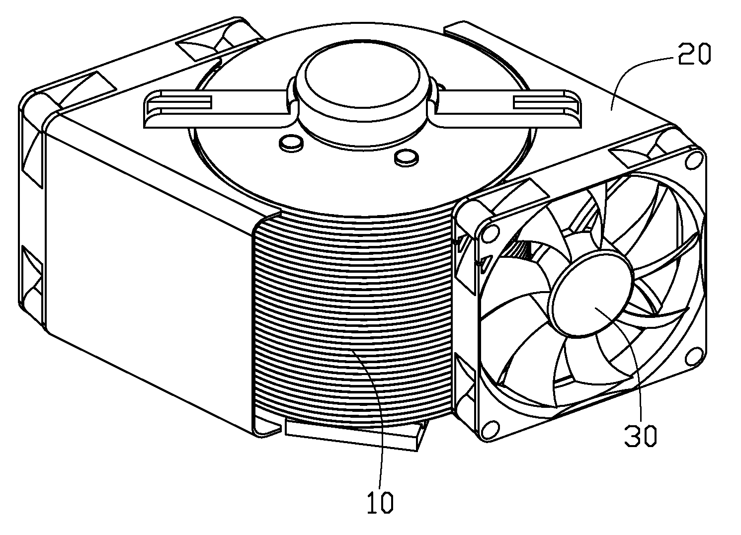
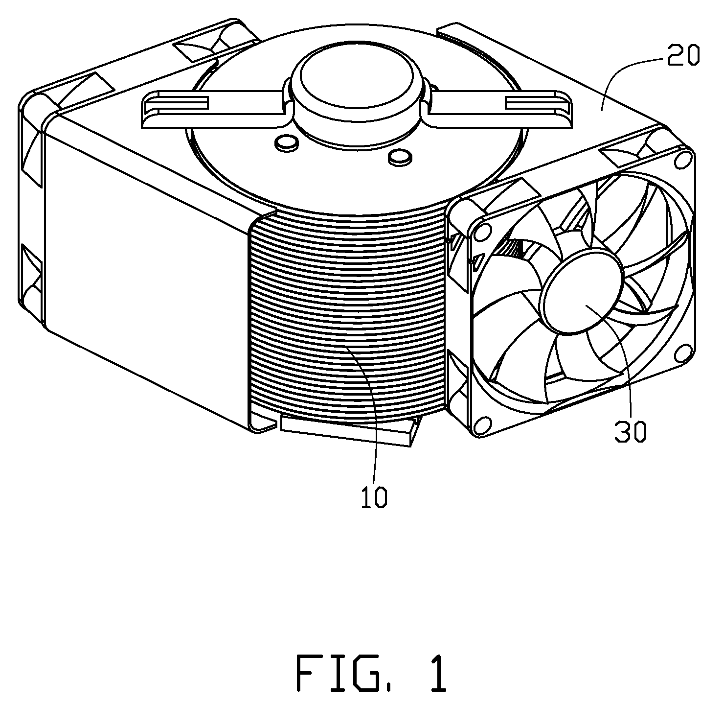
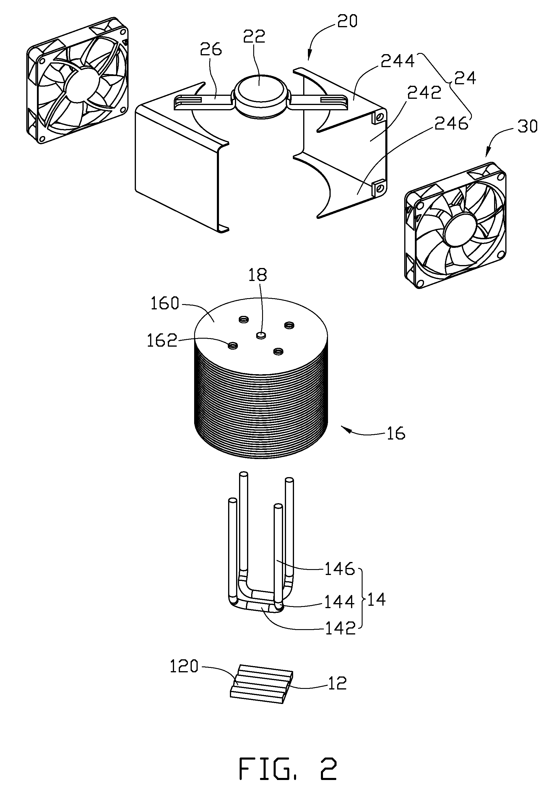
[0012]FIGS. 1 to 4 illustrate a heat dissipation device in accordance with an embodiment of the present disclosure. The heat dissipation device removes heat from an electronic device (not shown) and other electronic components (not shown) in the vicinity of the electronic device. The heat dissipation device comprises a heat sink 10, two fans 30 and a fixing member 20 pivotally connected to a top of the heat sink 10 to rotatably mount the fans 20 at a circumference of the heat sink 10.

[0013]The heat sink 10 comprises a base plate 12 in contact with the electronic device, a fin set 16, two heat pipes 14 thermally connecting the base plate 12 and the fin set 16 and a vertical retaining pole 18 extending through a centre of the fin set 16. The base plate 12 is rectangular and defines two elongated receiving grooves 120 therein. The two receiving grooves 120 are separated and perpendicular to two opposite lateral sides thereof. The fin set 16 is columnar and comprises a plurality of circ...


PUM


Abstract

A heat dissipation device removing heat from an electronic device includes a base plate, a fin set in thermal connection with the base plate, a fixing member and two fans. The fixing member includes a driving part coupled to a top of the fin set, two mounting parts located at two opposite sides of a circumference of the fin set and two connecting arms extending outwardly from the driving part and connecting with the two mounting parts. The two fans, respectively mounted on the two mounting parts of the fixing member and located at two opposite sites of the circumference of the fin set, are driven to rotate around the circumference of the fin set by the driving part and generate two streams of airflow which flow through the fin set that are non-intersecting.

Description

BACKGROUND OF THE INVENTION[0001]1. Field of the Invention[0002]The disclosure relates generally to heat dissipation, and more particularly, to a heat dissipation device incorporating fans to produce airflow in different directions.[0003]2. Description of Related Art[0004]It is well known that, during operation, computer electronic devices such as central processing units (CPU) generate large amounts of heat. The heat must be quickly removed from the electronic device to prevent instability or damage. Typically, a heat sink is attached to an outer surface of the electronic device to absorb heat from the electronic device, and the heat absorbed by the heat sink is dissipated to ambient air.[0005]Generally, in order to improve heat dissipation efficiency of a heat sink, a fan and heat pipes are applied to the heat sink. Usually, the fan is fixed in a determined position of a top or a lateral side of the heat sink by a fan holder and cannot be redirected. Thus, the fan of the heat diss...

Claims


Application Information

Patent Timeline
Patent Type & Authority Patents(United States)
IPC IPC(8): H05K7/20
CPCH01L23/3672H01L23/427H01L23/467H01L2924/0002H01L2924/00
Inventor XU, SHOU-BIAOZHOU, SHI-WENCHEN, CHUN-CHI
Owner FU ZHUN PRECISION IND SHENZHEN
Why Eureka
Try Eureka