Windage braking

a technology of windage brake and windage rod, which is applied in the direction of lifting frames, lifting devices, sport apparatus, etc., can solve the problems of no way of adjusting the speed of the fan relative to the speed of the spool, difficulty in controlling, and very rapid unwinding of the line, so as to save time and cost, high strength, and strong and robust

Active Publication Date: 2011-11-22
DROP ZONE UK
View PDF17 Cites 8 Cited by
  • Summary
  • Abstract
  • Description
  • Claims
  • Application Information

AI Technical Summary

Benefits of technology

[0009]It is a further object of the invention to provide a more compact windage brake that may be transportable and have a fan that can rotate at a different (typically, higher) speed than the spool.
[0011]Preferably the spool has a taper along the first axis from a relatively large diameter part to a relatively small diameter part and the free end of the line extends initially from the large diameter part of the spool and in use the line is drawn off down the taper. The spool may have a generally cylindrical portion extending axially from the small diameter part so that, after the fan has been accelerated by the effect of the taper, it then runs at substantially constant speed thereby to provide a substantially constant braking force and thereby a steady rate of descent.
[0013]The drive mechanism may comprise one or more drive belts, and at least one of such drive belts preferably interconnects a first drive pulley connected to the spool and a second drive pulley connected to the fan, the first drive pulley being of greater working diameter than the second drive pulley. In the operation of this arrangement, the fan rotates faster than the spool and thereby an appropriate braking force can be obtained from a relatively small fan. One of the drive pulleys may be replaceable by another drive pulley of different working diameter, so that the braking force can be conveniently adjusted. Preferably the or each drive belt is toothed.
[0015]If the windage brake is compact it can be transported and installed at any desired location as a complete assembly, saving time and cost and helping to ensure that the brake is safe by permitting pre-installation testing. A compact brake requires a compact spool, and this in turn necessitates a line which can be bent repeatedly to a small radius as well as being strong and robust. To this end the line preferably comprises a braid of gel-spun polyethylene filaments with high strength, high modulus and low creep.
[0016]The benefit of compactness is reduced if the brake needs to be assembled at the elevated installation location. Therefore the windage brake is preferably incorporated in regulating apparatus for regulating the descent of a person from an elevated position, the brake being carried in a frame for securing the apparatus assembled at the elevated position. For quick and convenient installation the regulating apparatus may include karabiners for securing the apparatus assembled at the elevated position. Preferably a harness is provided at the free end of the line for attaching the line to said person.

Problems solved by technology

First, the speed of rotation of the fan is identically that of the spool, so to get the fan to the high speed necessary to slow the jumper's descent before landing requires the line to unwind very quickly, which may be difficult to control.
Second, there is no way of adjusting the speed of the fan relative to that of the spool.
Third, having the fan secured to the spool results in an assembly with a long axial dimension and hence generally bulky and requiring a permanent mounting.

Method used


Image

  • Windage braking
  • Windage braking
  • Windage braking

Examples


Embodiment Construction

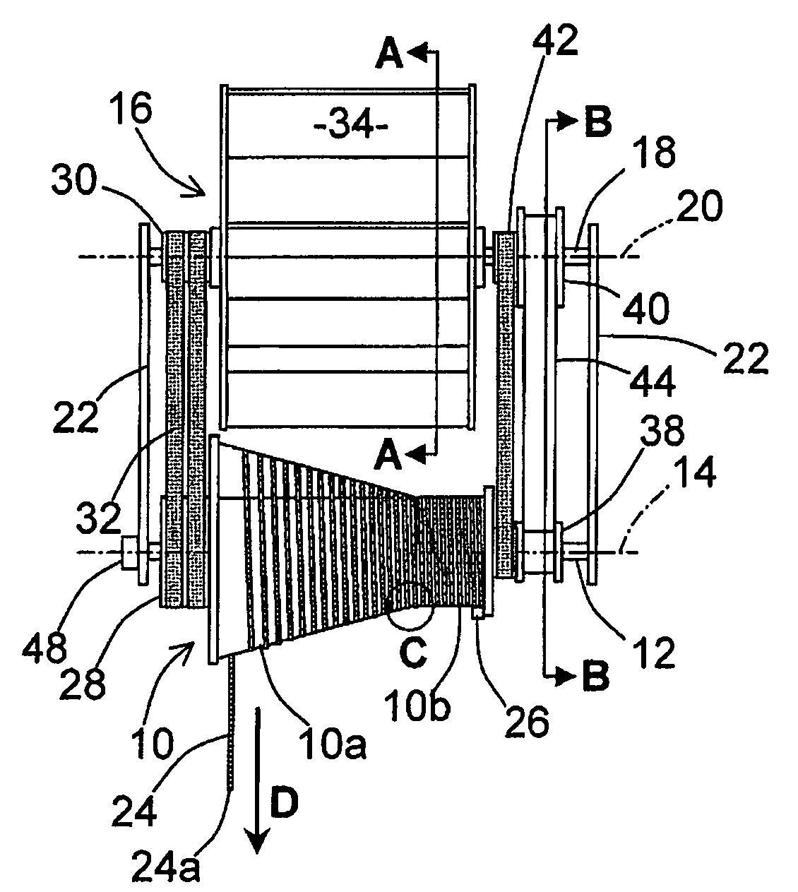
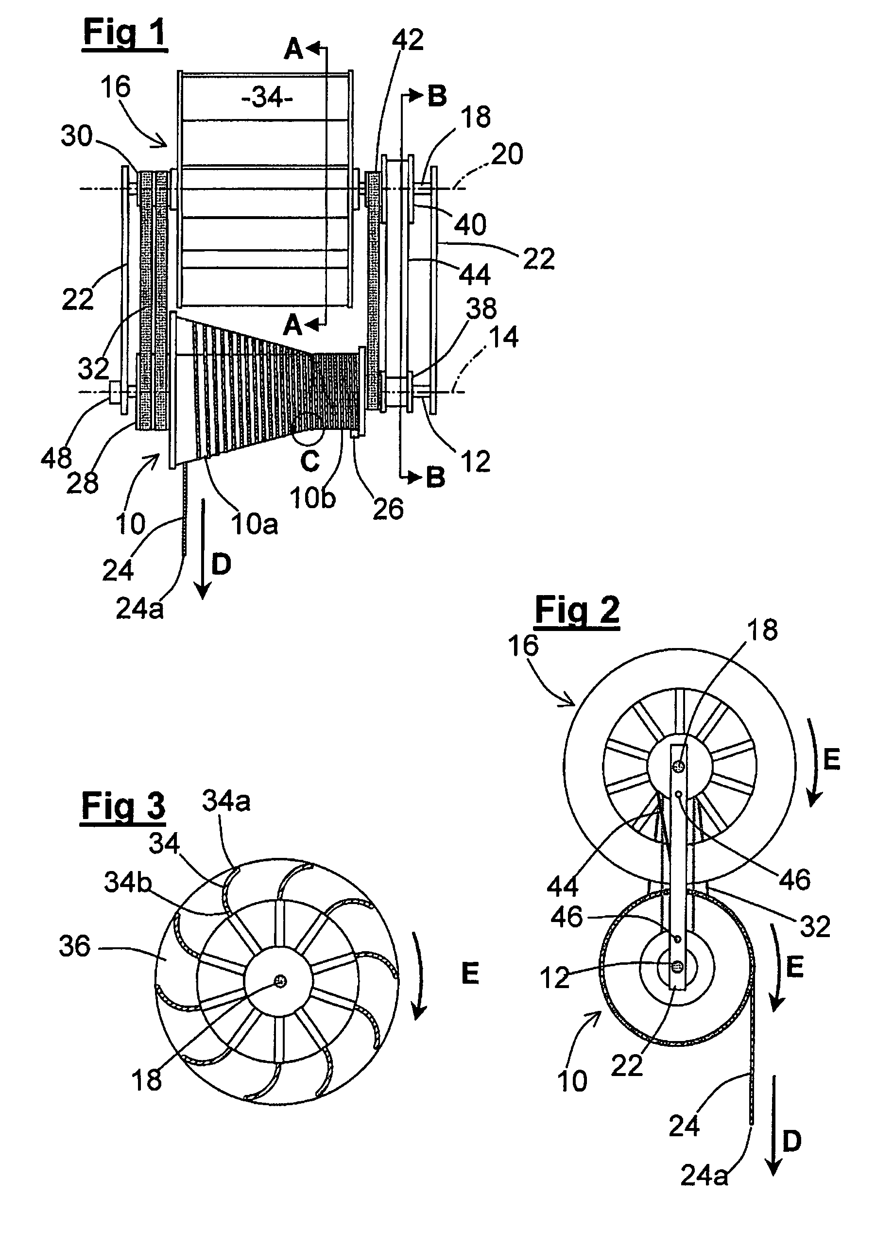
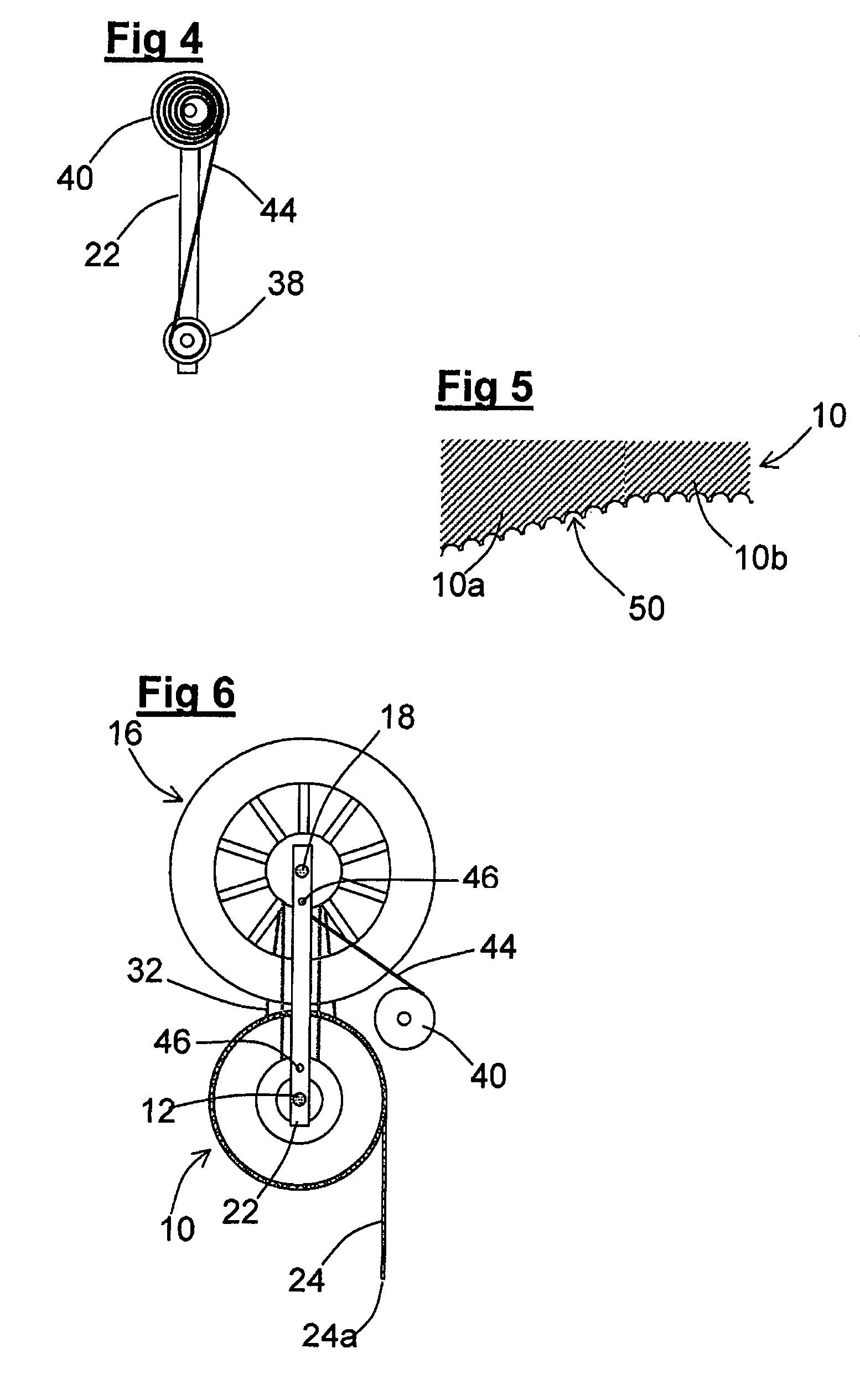
[0026]Referring first to FIGS. 1 and 2, the windage brake shown therein comprises a spool 10 mounted on a spindle 12 to be rotatable about a first axis 14 and a fan 16 mounted on a spindle 18 to be rotatable about a second axis 20 parallel to the first axis 14. The spindles 12 and 18 extend between a pair of end plates 22 thereby forming a frame to carry the windage brake. A line 24 having a free end 24a is wound helically upon the spool 10, its other end being secured to the spool 10 by a clamp 26. The line 24 is a braid of gel-spun polyethylene filaments with high strength, high modulus and low creep available under the registered trade mark Dyneema from DSM of The Netherlands.

[0027]Secured to one end (the left hand end as seen in FIG. 1) of the spool 10 and rotatable about the spindle 12 is a first drive pulley 28. Secured to the left hand end of the fan 16 and rotatable therewith about the spindle 18 is a second drive pulley 30. A pair of drive belts 32 interconnect the pulleys ...


PUM


Abstract

A windage brake for a fan descender comprises a rotatable spool connected by drive belts to a fan comprising a radial flow air impeller. A line is wound helically upon the spool. A user of the fan descender puts on a harness (not shown) at the free end of the line and jumps from an elevated position. The line is thereby drawn off the spool and rotates it. The rotating spool drives the fan and also winds a power spring formed by a resilient strip. The windage of the fan regulates the descent of the jumper, the fan being accelerated to a speed at which the braking force is such that the jumper descends at a rate safe for landing on the ground. When the jumper is on the ground, he removes the harness and releases the free end of the line. The line is then automatically retrieved by the power spring and rewound on the spool.

Description

CROSS REFERENCE TO RELATED APPLICATIONS[0001]This application claims priority from United Kingdom Patent Application No. 06 05 563.6, filed 20 Mar. 2006, the entire disclosure of which is incorporated herein by reference in its entirety.TECHNICAL FIELD[0002]This invention concerns a windage brake, which is to say apparatus employing air drag upon a rotating device to limit the speed of a moving item. The invention is particularly but not necessarily exclusively applicable to fan descenders and the like.BACKGROUND OF THE INVENTION[0003]A fan descender provides an exhilarating experience for adventure-minded individuals. It comprises an elevated platform (which may form part of or be set upon a tower, a bridge, a crane cradle, a building or a tree etc) from which a user jumps, his fall being controlled by a windage brake in the form of a fan rotated by a line connected to the jumper by means of a harness. If the line rotates the fan at a constant speed, the air drag on the fan is simi...

Claims


Application Information

Patent Timeline
Patent Type & Authority Patents(United States)
IPC IPC(8): A62B1/08
CPCA62B1/12A63B21/0088A63B21/153B66D5/026A62B1/10A62B1/00
Inventor MORIARTY, NICHOLAS
Owner DROP ZONE UK
Why Eureka
Try Eureka