RF transmitter with bias-signal-induced distortion compensation and method therefor

a technology of bias signal and compensation method, which is applied in the field of radiofrequency (rf) transmitters, can solve the problems of amplified rf signal output from rf power amplifiers to spill outside the frequency range, distortion, and unwanted intermodulation,

Inactive Publication Date: 2011-11-22
CRESTCOM INC
View PDF47 Cites 8 Cited by
  • Summary
  • Abstract
  • Description
  • Claims
  • Application Information

AI Technical Summary

Benefits of technology

[0013]It is an advantage of at least one embodiment of the present invention that an improved RF transmitter with bias-signal-induced distortion compensation and method of operating the RF transmitter are provided.
[0015]Another advantage of at least one embodiment of the present invention is that a variably biased RF transmitter and method are provided which decouple, to a large degree, controls provided to improve power-added efficiency from controls provided to improve linearization.
[0016]Another advantage of at least one embodiment of the present invention is that an RF transmitter is configured to cancel distortion caused by the use of non-DC signals for biasing an RF power amplifier.

Problems solved by technology

The degree to which the amplification is not perfectly linear leads to distortion, unwanted intermodulation, and spectral regrowth in the amplified RF signal output from the RF power amplifier.
Spectral regrowth can cause the amplified RF signal output from the RF power amplifier to spill outside the frequency band where the transmitter is licensed to operate.
Other forms of distortion, though nevertheless confined within the licensed frequency band, cause deterioration in an error vector magnitude (EVM) parameter of the amplified RF signal output from the RF power amplifier.
Unfortunately, a typical amplified RF signal is an extremely complex composite of wanted and unwanted signal components.
The unwanted signal components result from many different distorting effects.
Accordingly, while many diverse schemes have been directed toward the problem of improving RF amplifier linearity, few have actually achieved a highly linear result.
But when DC biasing is used, poor efficiency usually results.
That goal has been difficult to meet.
But a significant price is typically paid in linearity by this technique.
Accordingly, the EER technique is not readily useable in high power and wide bandwidth applications because, rather than realizing efficiency enhancement, efficiency deterioration is the likely result along with reduced linearity.
Efficiency deterioration would result from attempting to generate a high power bias voltage that exhibits a bandwidth consistent with the amplitude content of a wide bandwidth signal.
But a linearity penalty still results, and the envelope-following technique is not readily usable in high power and wide bandwidth applications because, rather than realizing efficiency enhancement, efficiency deterioration is the likely result.
But a linearity penalty still results, and nothing is provided to ensure that the linearity penalty does not result in the violation of a spectral mask.
But none of these efficiency techniques are as compatible as desired with a transmitter application that calls for the use of a highly linear or highly linearized RF power amplifier.

Method used


Image

  • RF transmitter with bias-signal-induced distortion compensation and method therefor
  • RF transmitter with bias-signal-induced distortion compensation and method therefor
  • RF transmitter with bias-signal-induced distortion compensation and method therefor

Examples


Embodiment Construction

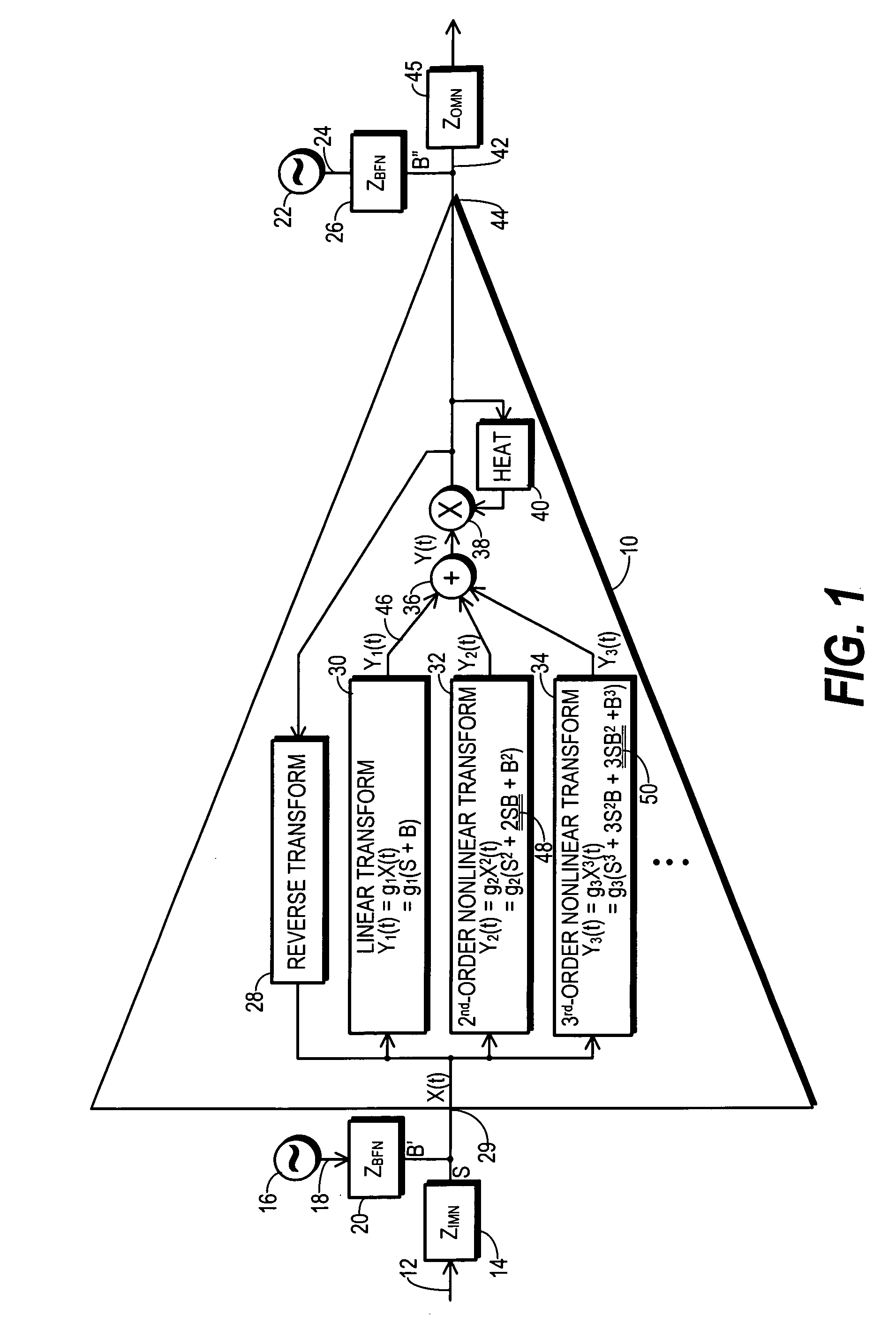
[0023]FIG. 1 shows a block diagram of a model which characterizes, at least in part, the performance of a generic RF amplifier 10 for purposes of the present discussion. Those skilled in the art will appreciate that the model depicted in FIG. 1 provides a representation of how RF amplifier 10 appears to operate and does not represent an actual physical device. The model of FIG. 1 is provided for purposes of teaching the nature of signals that are relevant to a particular type of distortion introduced through the operation of RF amplifier 10 with non-DC bias signals. Other models may be more suitable for other purposes.

[0024]An RF analog communication signal 12 is provided to an input of RF amplifier 10 through an impedance 14 of an input matching network (ZIMN). RF communication signal 12 has been modulated to convey the data whose communication is the purpose of a transmitter where RF amplifier 10 resides.

[0025]A bias signal generator 16 generates a bias signal 18, and bias signal ...


PUM


Abstract

An RF transmitter (60) generates non-DC bias signals (104, 106) configured to improved power-added efficiency (PAE) in the operation of an RF amplifier (94). The RF amplifier (94) generates an amplified RF signal (126) which, due to the addition of the bias signals (104, 106), includes bias-signal-induced RF distortion (48, 50). The bias signals (104, 106) drive a bias-induced distortion cancellation circuit (152) that adjusts the bias signals to compensate for the influence of impedances experienced by the bias signals (104, 106) before being applied to the RF amplifier (94). After mixing with a baseband communication signal (64), adjusted bias signals (186, 188) are combined into a composite baseband signal (76), upconverted to RF in an upconversion section 84, and applied to the RF amplifier (94) where they cancel at least a portion of the bias-signal-induced RF distortion (48, 50).

Description

RELATED INVENTIONS[0001]This patent is related to: “RF Transmitter with Variably Biased RF Power Amplifier and Method Therefor,” filed 2 Jun. 2006, Ser. No. 11 / 445,816, US Publication No. 2007 / 0281635, Published 6 Dec. 2007, and to “Distortion-Compensated RF Transmitter and Method Therefor,” filed 10 Oct. 2007, Ser. No. 11 / 870,021, each of which is incorporated herein, in its entirety, by reference.TECHNICAL FIELD OF THE INVENTION[0002]The present invention relates generally to the field of radio-frequency (RF) transmitters. More particularly, the present invention relates to biasing RF power amplifiers used in RF transmitters and to compensating for distortion which results from the application of bias signals.BACKGROUND OF THE INVENTION[0003]An RF power amplifier provides the final stage of amplification for a communication signal that has been modulated and converted into an RF signal. The RF signal provided to an RF power amplifier for amplification generally exhibits frequencie...

Claims


Application Information

Patent Timeline
Patent Type & Authority Patents(United States)
IPC IPC(8): H04B1/04H04B17/00
CPCH03F1/0211H03F1/0266H03F1/3205H03F1/3247H03F3/193H03F3/245H04B1/04H03F2200/15H03F2200/18H04B2001/0433H03F1/34H03F3/24
Inventor MCCALLISTER, RONALD DUANE
Owner CRESTCOM INC
Why Eureka
Try Eureka