Method for constructing job operation environment

a construction method and operation environment technology, applied in multi-programming arrangements, instruments, computing, etc., can solve the problems of lack of conventional techniques in the scheme or the method to know these factors, and the construction of the job operation environment takes a long time, so as to reduce the number of operating system restarts, reduce construction time, and reduce the effect of construction tim

Inactive Publication Date: 2011-11-29
HITACHI LTD
View PDF18 Cites 7 Cited by
  • Summary
  • Abstract
  • Description
  • Claims
  • Application Information

AI Technical Summary

Benefits of technology

[0014]According to the present invention, since the construction time to construct the job operation environment can be estimated, it is possible to determine which one of the disk images is to be used to possibly reduce the construction time. According to the present invention, by optimizing the procedure to uninstall or to install application programs and patch programs, the construction time can be reduced as compared with a case in which the programs are uninstalled and are then installed in the ordinary sequence. Particularly, the scheme to reduce the number of operating system restarts is efficiently applicable to a job using a server computer including a large-capacity memory and / or a large-sized peripheral device. In such computer including a large-capacity memory and / or a large-sized peripheral device, when the computer is restarted, quite a long period of time is required to initialize and to check operation of its memory and its peripheral devices. Therefore, reducing the operating system restarts in the computer of this type is remarkably effective to minimize the construction time of the job operation environment.

Problems solved by technology

This leads to a problem that the construction of the job operation environment takes a long period of time.
The conventional technique lacks in the scheme or the method to know these factors.

Method used


Image

  • Method for constructing job operation environment
  • Method for constructing job operation environment
  • Method for constructing job operation environment

Examples


first embodiment

[0043]Next, referring to the drawings, description will be given of a first embodiment of the present invention.

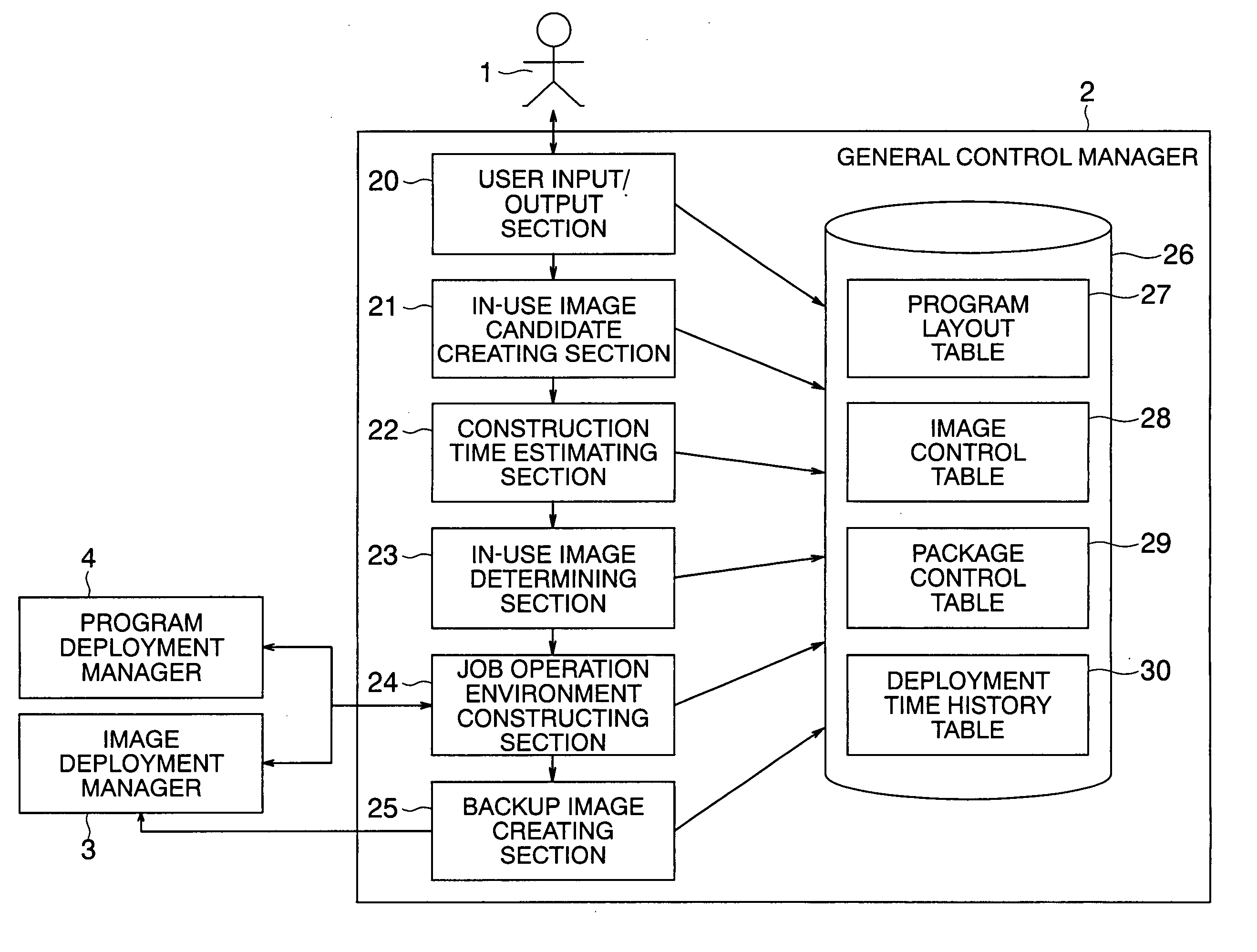
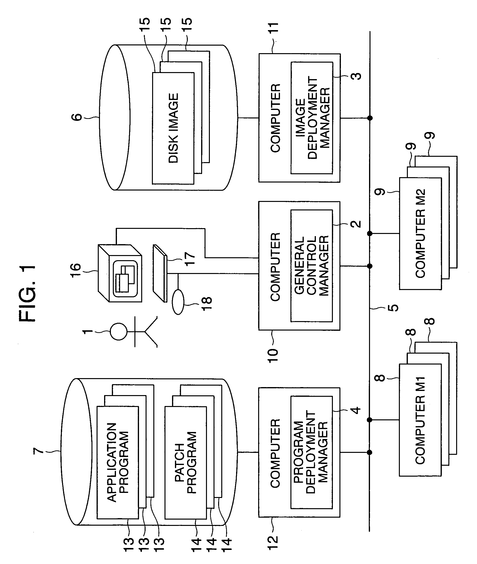
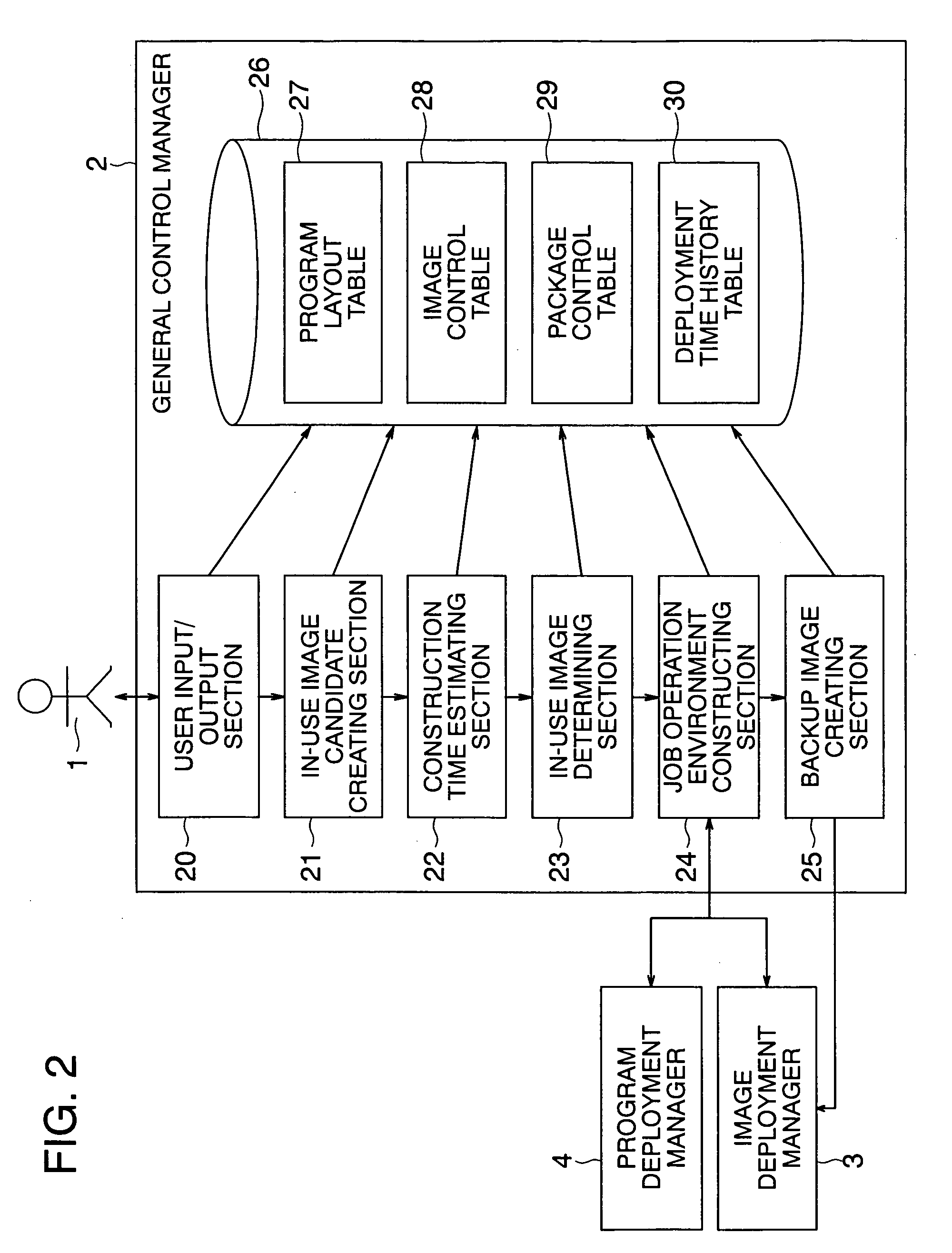
[0044]FIG. 1 shows an overall configuration of the first embodiment of a computer system for job operation in a block diagram. The system includes a computer 10 on which programs of a general control manager 2 operate, a computer 11 on which an image deployment manager 3 operates, a computer 12 on which a program deployment manager 4 operates, a computer 8 of type M1, a computer 9 of type M2, a disk image storage 6, and a program package storage 7. The system includes a plurality of computers 8 and a plurality of computers 9. Each of the computers 8 and 9 may be an ordinary server computer or a blade server or may be implemented by logically dividing one computer.

[0045]The computers 8 to 12 are connected via a network 5 to each other to be mutually communicable with each other. Job programs operate on the computer 8 or 9. When the manager 1 supplies an instruction to the g...

second embodiment

[0250]Description will now be given of another embodiment configured by modifying part of the first embodiment.

[0251]In the flowchart of FIG. 16, Step 2110 in which the manager 1 determines an in-use program layout name corresponding to the in-use disk image is employed in place of Step 2101 to obtain an in-use program layout name corresponding to the in-use disk image. In Step 2110, an input user interface for the manager 1 to determine an in-use program layout name is presented on the display 16. According to information inputted by the manager 1 using the keyboard 17 and the mouse 18, an in-use program layout name is determined.

[0252]FIG. 25 is an input user interface for the manager 1 to determine the in-use program layout name in Step 2110. The widow 200 of FIG. 25 is a window representing the input user interface for the manager 1 to determine the in-use program layout name. Each rectangular area 201 displays information items to construct a job operation environment using a d...

third embodiment

[0256]Description will now be given of another embodiment implemented by partially modifying the first or second embodiment of the present invention.

[0257]FIG. 26 is a compatible program name table 31 used in the present embodiment. The table 31 includes a column of a program name 140 and a column of a compatible program name 14. The program name 140 stores a program name. The compatible program name 141 stores a set of program names. Each of the program names in the column 141 provides a function compatible to the program indicated by the column 140. That is, the programs of the program names in the column 141 can be equivalently used for the program of column 140.

[0258]In the embodiment, the steps shown in FIG. 27 are inserted between Steps 1106 and 1107 of FIG. 9. In the processing of FIG. 27, if a disk image under consideration does not include any program which does not exist in list A obtained in Step 1001, but includes a program compatible with a program included in list A, t...


PUM


Abstract

To construct an operation environment for a job by deploying in a computer an operating system and various programs as a premise of operation of a job program of the job of which operation is to be started in a job system, there is selected an optimized construction procedure requiring the shortest construction time. Various application programs and patch programs for the deployment included in the saved disk images are compared with the various programs as a premise of the job operation to obtain a period of time to uninstall unnecessary programs, a period of time to install lacking programs, and a period of time to deploy the disk image on the computer. An estimated construction time is obtained by adding the periods of time to each other. By optimizing the uninstallation and installation procedure, the estimated construction time is reduced to the maximum extent.

Description

INCORPORATION BY REFERENCE[0001]The present application claims priority from Japanese application JP2006-040123 filed on Feb. 17, 2006, the content of which is hereby incorporated by reference into this application.BACKGROUND OF THE INVENTION[0002]The present invention relates to a technique for use with a system including a large number of computers such as a blade server for constructing a job operation environment by use of a boot disk image.[0003]To initiate operation of a job using computers such as a Web three-tier job, it is required to construct an operation environment in which a job intrinsic application and job intrinsic data are deployed. The job operation environment is constructed in the following procedure. First, there is determined a computer to conduct operation of the job. Next, an operating system (OS), device drivers, application programs and patch programs to remove faults of the operating system and to expand functions of the operating system are installed in ...

Claims


Application Information

Patent Timeline
Patent Type & Authority Patents(United States)
IPC IPC(8): G06F9/445
CPCG06F8/61G06F8/63
Inventor IIZUKA, DAISUKE
Owner HITACHI LTD
Why Eureka
Try Eureka