Helmet shield attaching mechanism, and helmet attached with the same

a technology of attaching mechanism and helmet, which is applied in the direction of headwear caps, protective garments, hats, etc., can solve the problems of cumbersome operation of raising the fully-closed shield, inconveniences following, and inability to smoothly move the original shield upward, etc., and achieves simple arrangement and effective correction

Active Publication Date: 2011-12-06
SHOEI CO LTD
View PDF48 Cites 9 Cited by
  • Summary
  • Abstract
  • Description
  • Claims
  • Application Information

AI Technical Summary

Benefits of technology

[0006]The present invention is aimed at effectively correcting the above drawbacks of the shield attaching mechanism of EP 1 293 138 A1 with a comparatively simple arrangement. It is an object of the present invention to provide a helmet shield attaching mechanism with which even if an anti-fogging auxiliary shield may or may not attach to the inner surface of a shield, when raising the shield which is in the substantially fully-closed state, the shield or anti-fogging auxiliary shield can move upward without catching on a window opening rim member for a head protecting body or the like.

Problems solved by technology

When using a helmet in which such an anti-fogging auxiliary shield attaches to an original shield, if the axial supports on the right and left sides of the head protecting body of the helmet merely axially support portions of the original shield near the right and left ends, the following inconveniences arise.
If the helmet wearer erroneously performs only one-step operation (that is, the operation of only pulling the shield upward), the original shield cannot smoothly move upward.
To smoothly move the original shield upward, the two-step operation as described above is necessary, and accordingly the operation of raising the fully-closed shield becomes cumbersome.

Method used


Image

  • Helmet shield attaching mechanism, and helmet attached with the same
  • Helmet shield attaching mechanism, and helmet attached with the same
  • Helmet shield attaching mechanism, and helmet attached with the same

Examples


first embodiment

A. First Embodiment

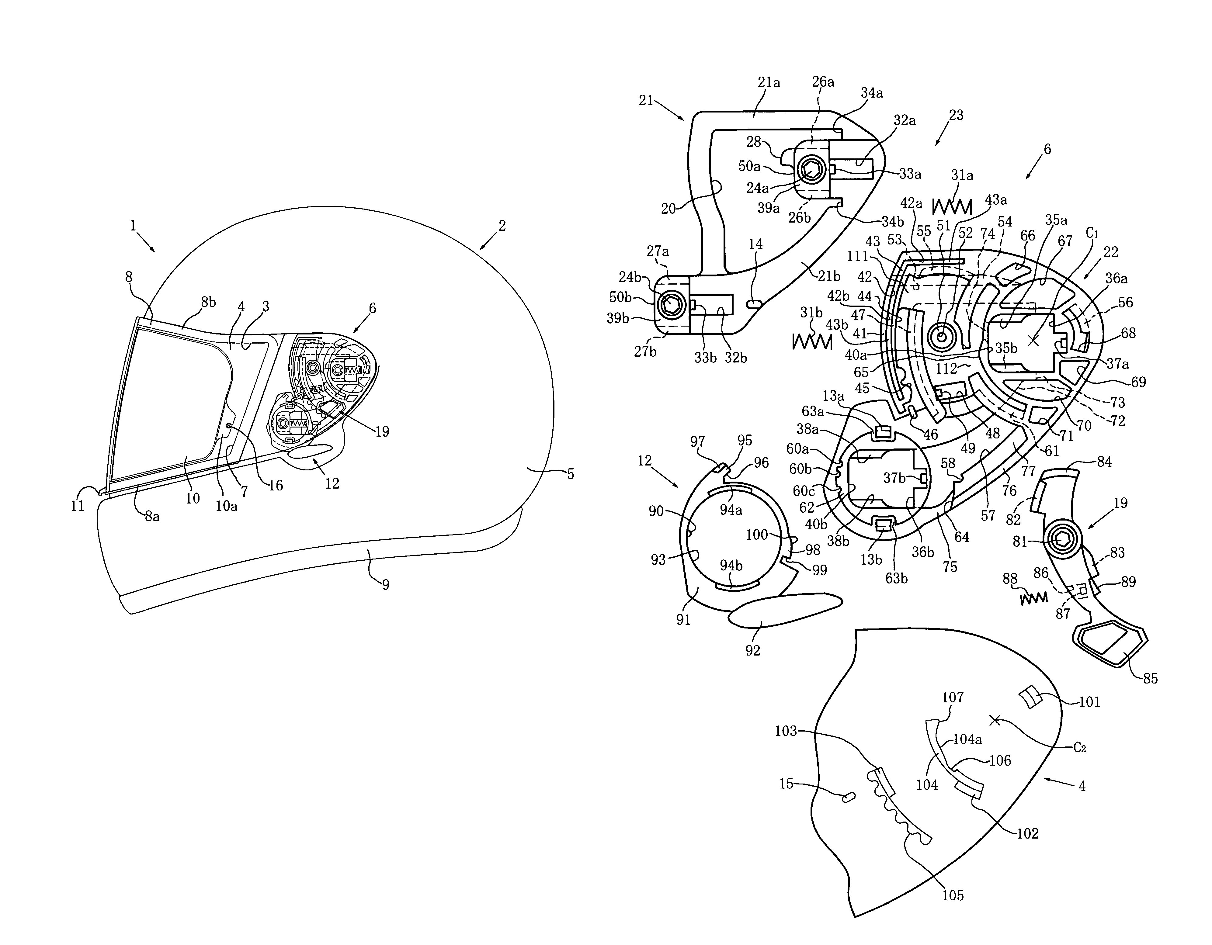
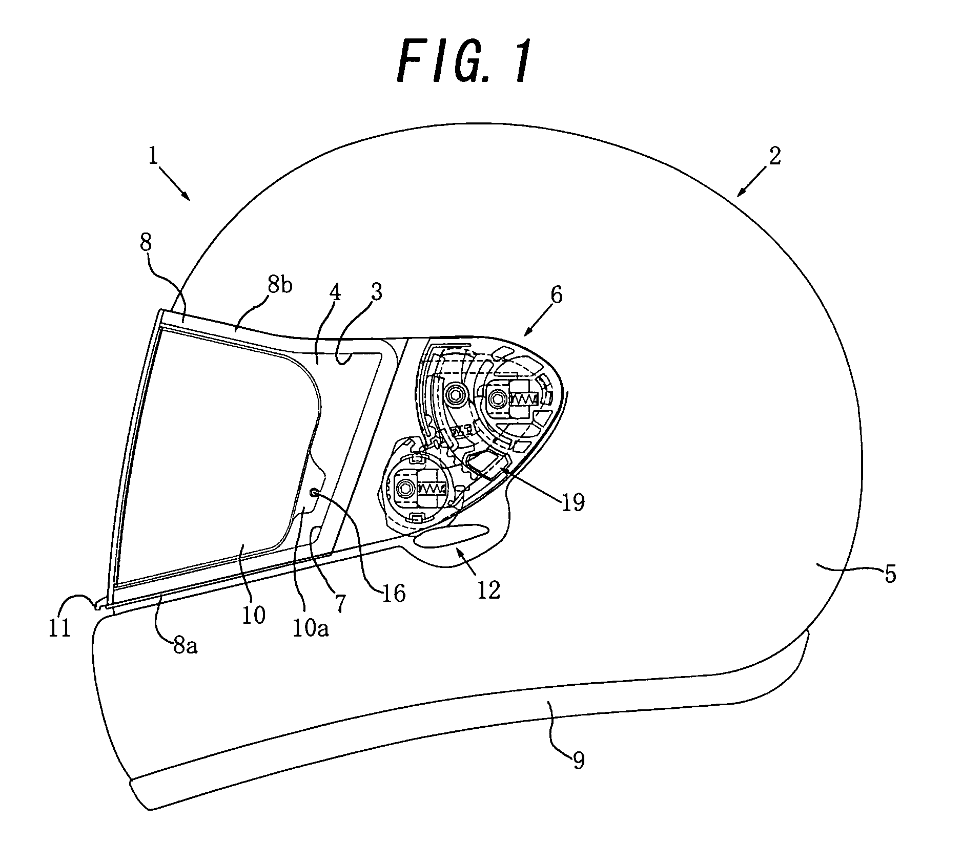
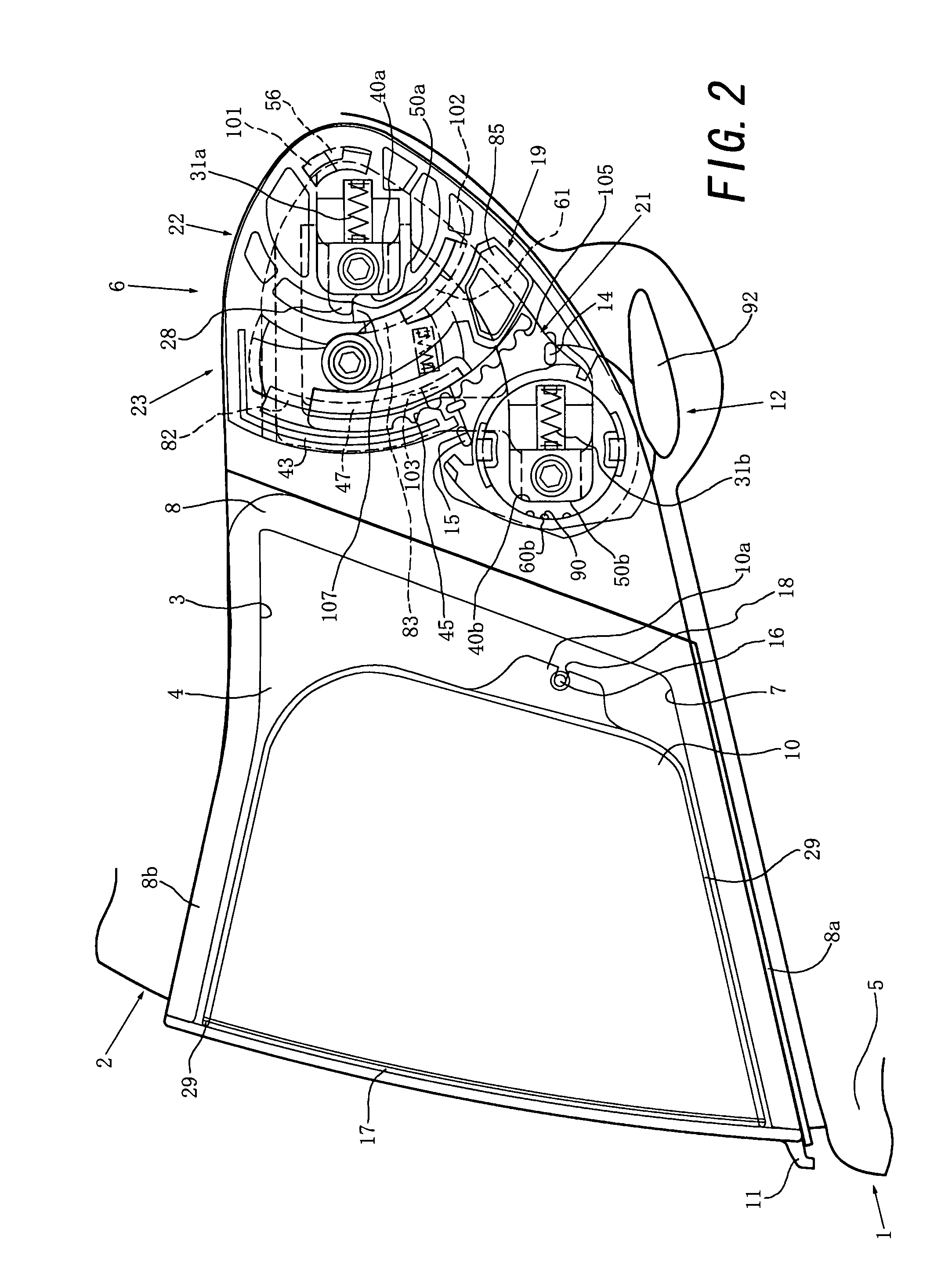
[0042]The first embodiment of the present invention will be described in “1. Schematic Arrangement of Helmet as a Whole”, “2. Arrangement of Shield Attaching Mechanism” and “3. Operation of Shield Attaching Mechanism” with reference to FIGS. 1 to 14.

[0043]1. Schematic Arrangement of Helmet as a Whole

[0044]As shown in FIG. 1, a full-face-type helmet 1 comprises a full-face-type head protecting body 2 to be worn on the head of a helmet wearer such as a motorcycle rider, an original shield (in other words, a main shield) 4 which can open / close a window opening 3 formed in the front surface of the full-face-type head protecting body 2 so as to oppose a portion between the forehead and chin (that is, the central portion of the face) of the helmet wearer, and a pair of right and left chin straps (not shown) attaching to the inner side of the head protecting body 2. Of the head protecting body 2, each of those portions which oppose the chin, forehead and the like of the ...

second embodiment

B. Second Embodiment

[0128]The second embodiment of the present invention will be described in “1. Schematic Arrangement of Helmet as a Whole”, “2. Arrangement of Shield Attaching Mechanism” and “3. Operation of Shield Attaching Mechanism” with reference to FIGS. 15 to 23. The second embodiment shown in FIGS. 15 to 23 can have substantially the same arrangement as that of the first embodiment described above except for the respects to be described below. Hence, in FIGS. 15 to 23, portions that are common with FIGS. 1 to 14 are denoted by the same reference numerals, and a repetitive description will be omitted where appropriate.

[0129]1. Schematic Arrangement of Helmet as a Whole

[0130]In the second embodiment, as shown in FIGS. 15 and 16, in place of the pair of right and left engaging slits 18 in the above first embodiment, a pair of right and left through holes 121 are formed near a pair of right and left tongue pieces 10a of an anti-fogging auxiliary shield 10. By fitting a pair of...


PUM


Abstract

A helmet shield attaching mechanism with which when raising a shield, the shield and / or an anti-fogging auxiliary shield will not catch on a window opening rim member for a head protecting body, in spite that the operation of raising the shield in a fully-closed state is comparatively simple and that the mechanism has a comparatively simple structure. The helmet shield attaching mechanism includes a stationary base member fixing to the head protecting body, a movable base member attaching to the stationary base member so as to be movable forward and backward with respect to the stationary base member, and the shield which is pivotally supported by the movable base member. When a substantially upward force acts on the shield which is in a fully-closed state, at least one cam follower provided to the shield or stationary base member relatively follows at least one cam surface formed on the stationary base member or shield, to move the shield forward substantially to the front side.

Description

TECHNICAL FIELD[0001]The present invention relates to a helmet shield attaching mechanism comprising a shield attaching base member attaching to a head protecting body, and a shield, a portion near one of the right and left ends of which pivotally attaches to the shield attaching base member, the shield attaching base member comprising a stationary base member fixing to the head protecting body, and a movable base member attaching to the stationary base member so as to be linearly reciprocally movable with respect to the stationary base member, and the shield being pivotally supported by the movable base member.[0002]The present invention also relates to a helmet comprising a left shield attaching mechanism provided to a left side of a head protecting body to pivotally support a portion of a shield near a left end thereof onto the head protecting body, and a right shield attaching mechanism provided to a right side of the head protecting body to pivotally support a portion of the sh...

Claims


Application Information

Patent Timeline
Patent Type & Authority Patents(United States)
IPC IPC(8): A42B1/08
CPCA42B3/222
Inventor ISOBE, EIJI
Owner SHOEI CO LTD
Why Eureka
Try Eureka