Refrigerant system unloading by-pass into evaporator inlet

a technology of refrigerant system and bypass, which is applied in the direction of liquid fuel engine, machine/engine, light and heating apparatus, etc., can solve the problems of lubricating oil degradation or damage to the internal compressor elements, the refrigerant mass flow through the evaporator is greater than the average, and the compressor could be damaged, etc., to achieve the effect of simplifying the replacement of the compressor

Active Publication Date: 2011-12-06
CARRIER CORP
View PDF9 Cites 4 Cited by
  • Summary
  • Abstract
  • Description
  • Claims
  • Application Information

AI Technical Summary

Benefits of technology

[0008]The present invention provides several benefits over the prior art that returns refrigerant from an intermediate compression point directly to the suction line. In this invention, the refrigerant from the compression point is returned upstream of the evaporator (preferably at a location between the main expansion valve and the evaporator entrance) instead of being returned downstream of the evaporator (at a location between the evaporator exit and compressor suction port). This results in a greater refrigerant mass flow through the evaporator during unloaded operation over the prior art. Increased refrigerant mass flow improves return flow of oil to the compressor during unloaded operation, increasing the efficiency of the evaporator by improving the heat transfer characteristics of the evaporator. Improved oil return also minimizes a risk of pumping the oil out of the compressor oil sump and storing it in the evaporator. If the oil is pumped out from the compressor, then the compressor could be damaged because bearings and other compressor elements may not receive adequate lubrication for proper operation.
[0010]In another feature, the prior art had an unloader by-pass valve just outside the compressor. As such, the valve and associated piping, etc. was often in the way should it become necessary to replace the compressor. By moving the by-pass line and the unloader by-pass valve away from the compressor toward the evaporator inlet, more space surrounding the compressor is created, which simplifies the compressor replacement. In yet another feature of this invention the compressor is provided with more than one unloader line and associated unloader by-pass valves. Each unloader line is connected at different compression points. With this arrangement one unloader line can be connected to return a partially compressed refrigerant upstream of the evaporator while the other unloader line can return a partially compressed refrigerant downstream of the evaporator. In yet another arrangement both unloader lines can be connected such that they both return the refrigerant upstream of the evaporator. Following the above logic even more than two unloader lines can be utilized in the present invention. A solenoid type valve is an example of the type of a by-pass valve for these applications, where the valve plunger is moved to alternate the valve opening between open and closed positions. In addition to the valve type where the by-pass valve is either fully open or fully closed for a prolonged period of time, a described by-pass valve can be selected to be a rapidly cycling valve; where the valve operates by a pulse width modulated control between open and closed position. The percentage of time that the valve is open determines the degree of modulation being achieved and the amount of flow by-passed through the valve. The valve cycling rate is normally selected to be shorter than the response time of the system. With this, the system responds as if the valve(s) is partially opened rather than being cycled between fully open and closed positions.

Problems solved by technology

This results in a greater refrigerant mass flow through the evaporator during unloaded operation over the prior art.
If the oil is pumped out from the compressor, then the compressor could be damaged because bearings and other compressor elements may not receive adequate lubrication for proper operation.
High refrigerant temperature entering the compressor is undesirable since it can overheat the motor driving the internal compressor elements, cause excessive discharge temperature and result in the lubricating oil degradation or damage to the internal compressor elements due to overheating.

Method used


Image

  • Refrigerant system unloading by-pass into evaporator inlet
  • Refrigerant system unloading by-pass into evaporator inlet
  • Refrigerant system unloading by-pass into evaporator inlet

Examples


Embodiment Construction

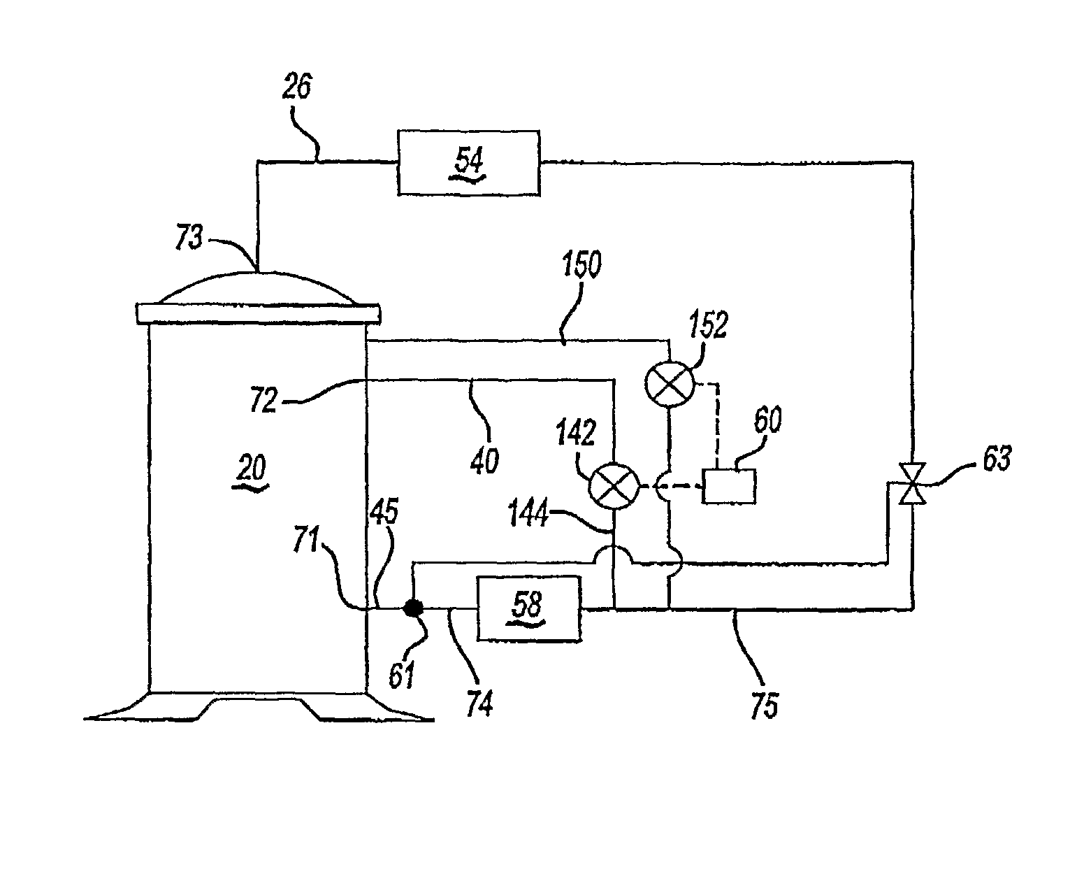
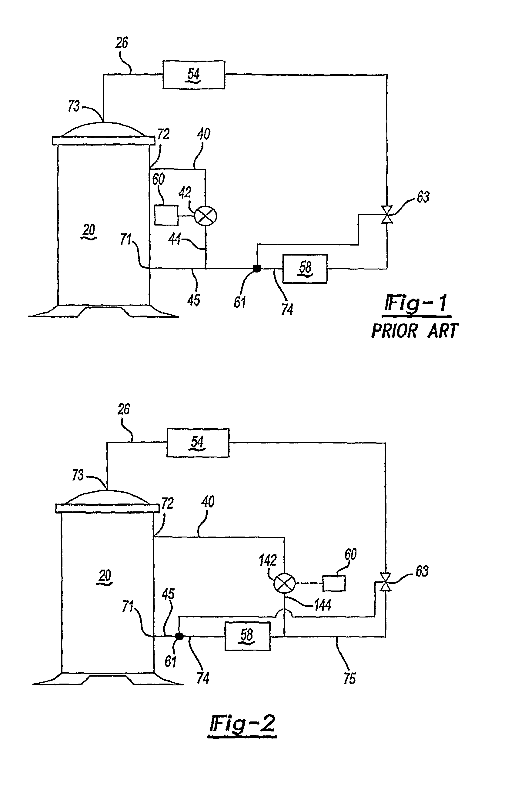
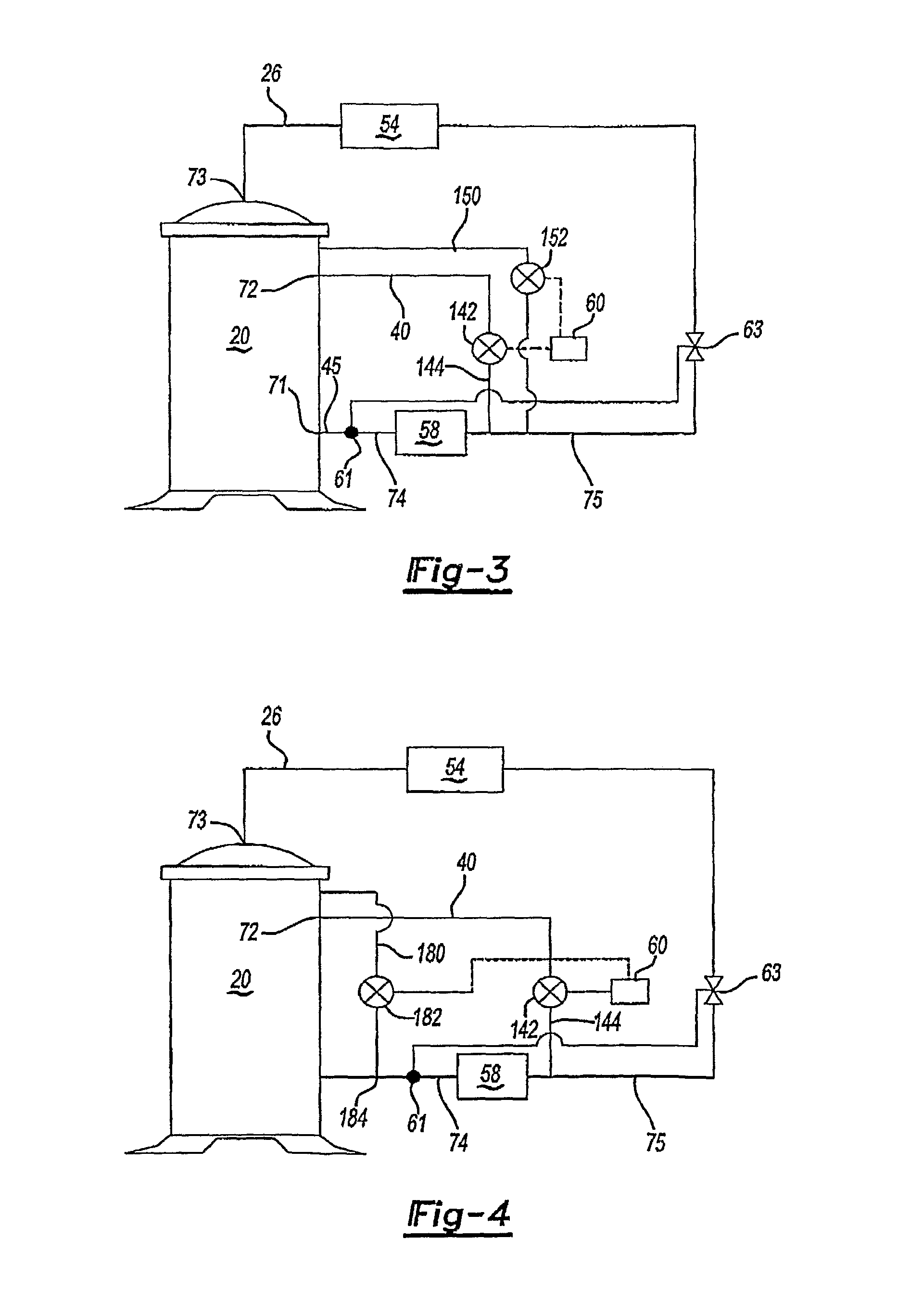
[0021]As shown in Prior Art FIG. 1, there is a compressor 20 that has a suction port 71, an intermediate compression port 72 and a discharge port 73. A line 40 establishes a communication between intermediate compression port 72 and suction line 45 through line 44.

[0022]As shown, a sensor 61 senses the condition of the refrigerant downstream of the evaporator 58 in line 74 and communicates with a main expansion device 63. It should be noted that a sensor 61 can, for example, be a feeler bulb of thermostatic expansion valve (TXV) or a temperature sensor of electronic expansion valve (EXV). However, regardless of the type of the sensor or expansion device type, the purpose of the sensor is to control the amount of main expansion device opening to achieve a desired amount of expansion of the refrigerant approaching the evaporator 58 such that the refrigerant leaving the evaporator 58 has a desired superheat amount upon entering compressor suction port 71. However, during unloaded opera...


PUM


Abstract

A refrigerant system has at least one unloader valve selectively communicating refrigerant between the compressor compression chambers and a point upstream of the evaporator. When the compressor is run in unloaded mode, partially compressed refrigerant is returned to a point upstream of the evaporator. In an unloaded mode, a higher refrigerant mass flow rate passes through the evaporator, as compared to prior art where the by-passed refrigerant was returned downstream of the evaporator. This increases system efficiency by more effectively returning oil which otherwise might be left in the evaporator back to the compressor. Also, the amount of refrigerant superheat entering the compressor in unloaded operation is reduced as compared to the prior art compressor systems, wherein the by-passed refrigerant is returned directly to the compressor suction line. Reduced refrigerant superheat increases system efficiency, improves motor performance and reduces compressor discharge temperature. Also, by moving the unloader line further away from the compressor, the compressor replacement is simplified as there is no connecting unloader line directly in front of the compressor.

Description

BACKGROUND OF THE INVENTION[0001]This invention relates to a unique placement for the connection between an unloader line valve and a lower pressure refrigerant line.[0002]One of the compressor types that are especially suited for this invention is a scroll compressor. Scroll compressors are becoming widely utilized in compression applications. However, scroll compressors present several design challenges. One particular design challenge is achieving reduced capacity levels when full capacity operation is not desired.[0003]Thus, scroll compressors, as an example, have been provided with unloader by-pass valves that divert a portion of the compressed refrigerant back to a compressor suction port. In this way, the amount of refrigerant compressed by a compressor is reduced. Of course, other compressor types may also have a by-pass valve for similar purpose, as for example, a screw compressor, where a by-pass valve can by-pass a part of refrigerant from the intermediate compression poc...

Claims


Application Information

Patent Timeline
Patent Type & Authority Patents(United States)
IPC IPC(8): F25B49/00F25B1/10
CPCF25B49/022F25B31/004F25B1/04F25B1/10F25B2400/0403F25B2400/0411F25B2600/0261F25B2600/2501F25B2600/2513F25B2700/21151F25B2600/0262F25B2600/2521
Inventor LIFSON, ALEXANDER
Owner CARRIER CORP
Why Eureka
Try Eureka