Starter motor

a technology of starting motor and starting gear, which is applied in the direction of electric motor starting devices, engine starters, machines/engines, etc., can solve the problems of increased manufacturing cost, difficult alignment, poor workability, etc., and achieves the effect of improving workability in assembly steps, reducing the number of steps, and improving product quality

Active Publication Date: 2011-12-06
MITSUBA CORP
View PDF15 Cites 0 Cited by
  • Summary
  • Abstract
  • Description
  • Claims
  • Application Information

AI Technical Summary

Benefits of technology

The starter motor of the present invention includes an idle gear that meshes with a ring gear of the engine and is supported by an idle shaft in a manner such that the idle gear is freely rotatable and movable in the axial direction, a covering member that supports both end parts of the idle shaft, and a shaft fixing member that is inserted from a mounting hole formed on the covering member to an insertion hole provided on the idle shaft. According to the starter motor of the present invention, the positioning part that is allocated in a predetermined position to make the mounting hole and the insertion hole face each other in a state in which the shaft fixing member can be inserted is provided on the idle shaft, therefore the mounting hole and the insertion hole can be aligned when the idle shaft is mounted. For this reason, in steps thereafter, checking of the positions of the holes and alignment of the holes become unnecessary, and workability in an assembly step is improved and also reduction in the number of steps can be attempted. In addition, work of adjusting the positions of the holes by holding the idle shaft becomes unnecessary, and a worker never touches the grease application section. In this manner, quality of a product is improved, and hands of the worker are not stained as well as the working environment can be improved.

Problems solved by technology

Therefore, there has been a problem in which workability is not excellent and also additional steps are necessary to thereby increase the manufacturing cost.
Therefore, alignment is difficult in comparison with a case in which the holes are at positions, such as positions in the right angle, where a reference can be easily set, and improvement in this respect has been required.
Further, a hand of the worker is stained at the time of alignment, which is not preferable in view of a working environment.
In addition, in case the insertion and the screwing of the idle shaft 153 are carried out in an automated line, a step of detecting whether the holes match with each other or not is difficult to be set, and has been an obstacle to automation of assembly of the starter motor 151.

Method used


Image

  • Starter motor
  • Starter motor
  • Starter motor

Examples


Embodiment Construction

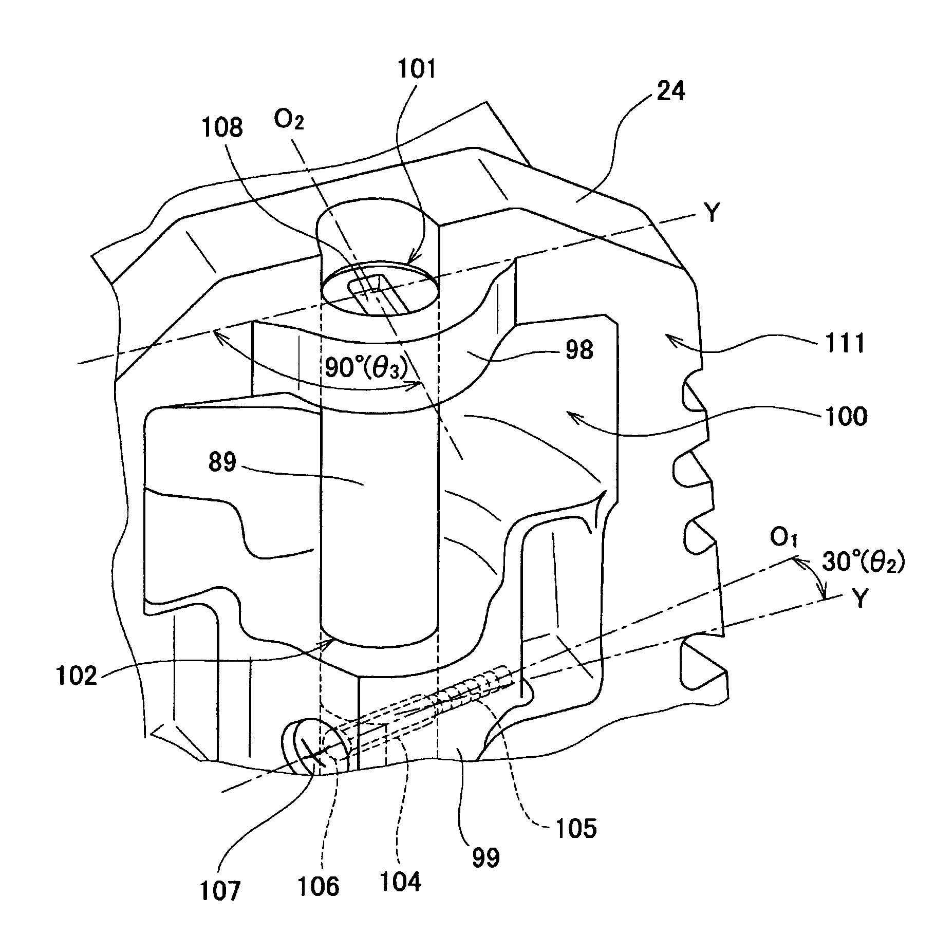
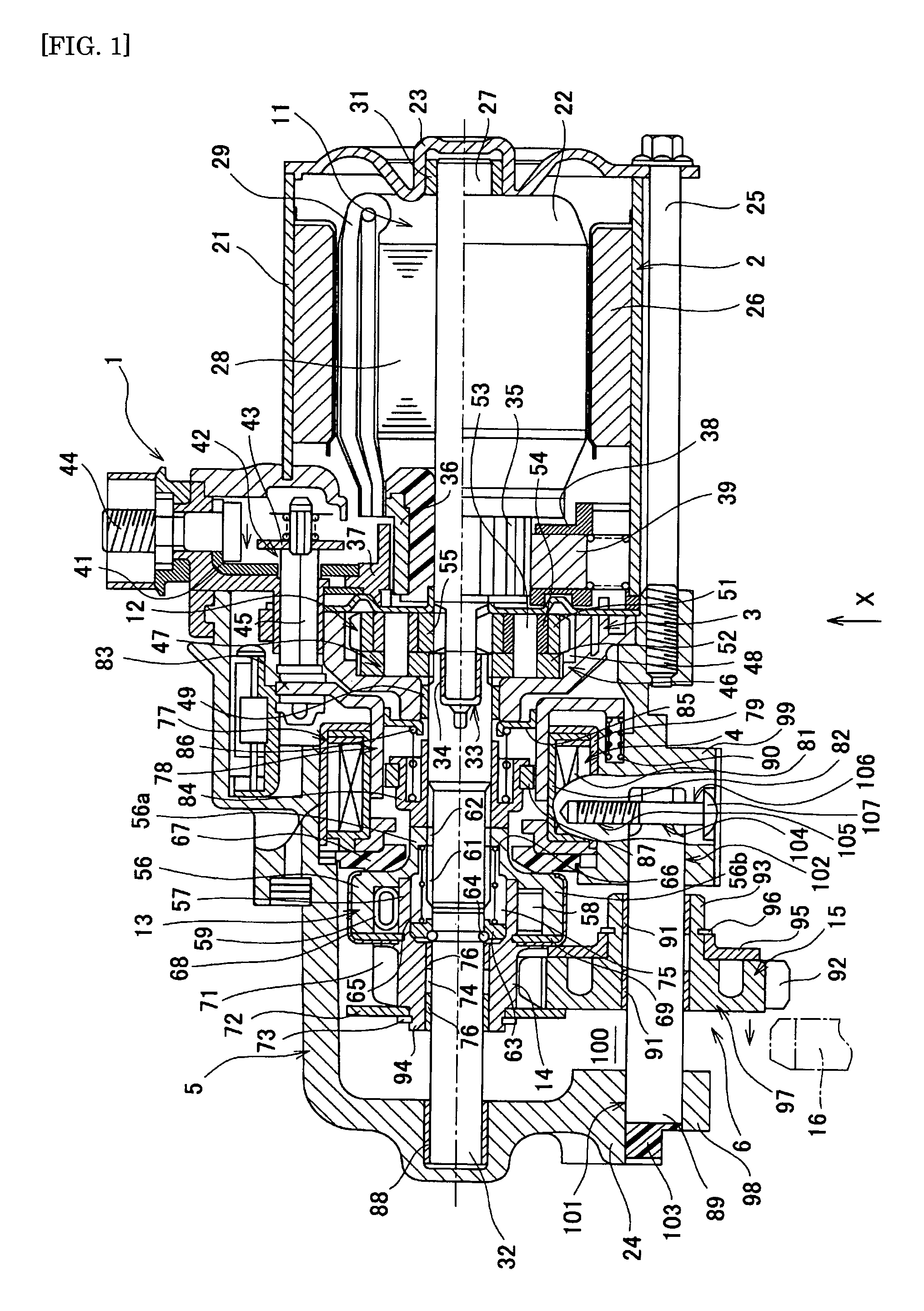
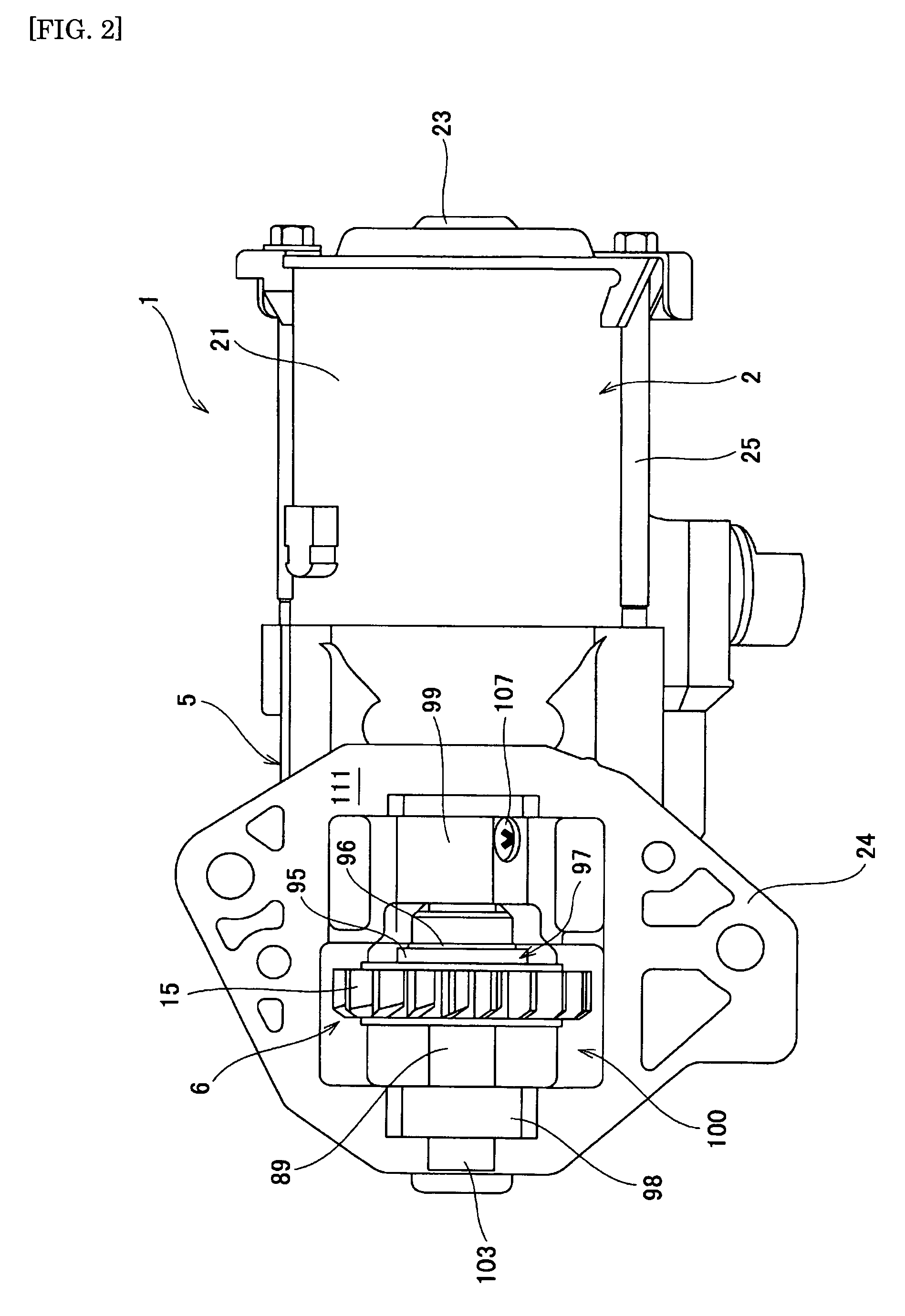
Now, the present invention will be described in greater detail by referring to the accompanying drawings. FIG. 1 is a cross-sectional view showing a configuration of a starter motor adopting an idle shaft positioning structure of the present invention, FIG. 2 is a bottom view (viewed from an angle X in FIG. 1) of the starter motor of FIG. 1. The electric starter motor 1 of FIG. 1 is used for starting an automotive engine, giving rotations to a resting engine required for intake, atomization, compression and ignition of fuel.

Roughly speaking, the electric starter motor 1 comprises a motor section 2, a gear section 3, a magnet switch section 4, a case section 5 and an idle section 6. In the motor section 2, there is provided a motor (electric motor) 11 as a driving source, and in the gear section 3, there are provided a planetary gear mechanism 12, an overrunning clutch 13 and a pinion 14 as reduction gears. In the idle section 6, there is provided an idle gear 15 engaging with the pi...


PUM


Abstract

A screw mounting hole and a female screw part are formed in a bearing part of a gear cover, and the screw insertion hole is formed in the idle shaft. The idle shaft is fixed to the gear cover by inserting a fixing screw through the screw mounting hole and screwing it into the female screw part through the screw insertion hole. A positioning groove in a predetermined position in relation to the screw insertion hole is formed in the end face of the idle shaft. When the positioning groove is disposed perpendicularly to an engine mounting surface and the idle shaft is fitted to the gear cover, the screw mounting hole is opposed to the screw insertion hole and, when the fixing screw is fitted, the confirmation of hole positions and the aligning of holes can be eliminated.

Description

TECHNICAL FIELDThe present invention relates to a starter motor mounted on an engine of an automobile or the like, and more particularly, to a positioning structure of an idle shaft that supports an idle gear meshing with a ring gear of an engine.BACKGROUND ARTIn engines used in automobiles, two-wheeled motor vehicles, and large generators, a starting operation is generally performed by a starter motor mounted on an engine. FIG. 7 is a perspective view showing an entire configuration of a starter motor 151 described above. The starter motor 151 is mounted on an engine (not shown) at an engine mounting surface 166 on a front side in the figure. The starter motor 151 is provided with an idle gear (middle gear) 152 that is movable in an axial direction and provided in a manner capable of meshing with and being separated from a ring gear (not shown) of the engine. The idle gear 152 is supported by an idle shaft 153 in a manner freely rotatable and movable in the axial direction, and mes...

Claims


Application Information

Patent Timeline
Patent Type & Authority Patents(United States)
IPC IPC(8): F02N15/06
CPCF02N11/00F02N15/00Y10T74/13Y10T74/137
Inventor SAITO, SHINYAHORIKOSHI, CHIHIROENKAKU, SHIGEYUKIONO, HITOSHI
Owner MITSUBA CORP
Why Eureka
Try Eureka