Connector for electronic detonators

a technology of electronic detonators and connectors, which is applied in the direction of electrical fuzes, coupling device connections, ammunition fuzes, etc., can solve the problems of imposing considerable load strains on detonator/signal transmission line contacts, prone to disruption of electronic detonators and associated signal transmission lines, and unavoidable degree of load

Active Publication Date: 2011-12-06
ORICA EXPLOSIVES TECH PTY LTD
View PDF35 Cites 61 Cited by
  • Summary
  • Abstract
  • Description
  • Claims
  • Application Information

AI Technical Summary

Benefits of technology

[0015]It is another object of the present invention, at least in preferred embodiments, to provide a connector for substantially preventing unwanted disruption of a signal transmission line / detonator connection by a tensile force applied to the signal transmission line.
[0017]In one aspect, the present invention provides for a connector that improves the security of connections between signal transmission lines and electronic detonators. Through detailed experimentation, the inventors of the present invention have developed a connector that may be suitably affixed to a detonator preferably adapted to receive the connector. Preferably, the connector is affixed on a non-actuating end of a detonator. Such a connection avoids the need for direct connection between the component wires of a signal transmission line and an electrical component of an electronic detonator. The connector confers significant durability to the signal transmission line / detonator connection, particularly with respect to tensile forces applied to the signal transmission line. In effect, the connector can substantially prevent breakage of the electrical contact and retain physical association between a signal transmission line and components of a detonator, even in the presence of fairly high tensile forces. Moreover, the connector of the present invention avoids the need for complex junction blocks or plug / plug socket systems of the prior art, and may be used, at least in preferred embodiments, in modular blasting apparatuses.
[0021]Preferably, each retaining means comprises a part of said at least one bridge element in contact with said insulating material, said part comprising at least one surface that extends at an angle to a direction of force applied to said at least one bridge element by pulling or tugging one of said parts that emerge from said plug member, thereby causing said at least one bridge element to resist slippage between said at least one bridge element and said plug member.
[0024]Preferably said at least one bridge element comprises a first end and a second end, each first end being adapted for attachment to a signal transmission line, and each second end being adapted for contact with an electrical component of the detonator. More preferably, each first end comprises a wire clasp or crimp for grasping the end of a wire emerging from the signal transmission line. Preferably, said electrical component is selected from the group consisting of: a printed circuit board or a component thereof, means to allow protection from electrostatic damage to other electronic components of the detonator, a resistor, a varistor, a zener diode, a suppressor diode, an encapsulated integrated circuit, an SO8 packaging, a filter, a capacitor, a spark gap, a small outline integrated circuit, and a rectifier, or alternatively said electrical component is connected to a printed circuit board or a component thereof, means to allow protection from electrostatic damage to other electronic components of the detonator, a resistor, a varistor, a zener diode, a suppressor diode, an encapsulated integrated circuit, or an SO8 packaging, a printed circuit board or a component thereof, a resistor, a filter, a capacitor, a spark gap, a small outline integrated circuit, or a rectifier. Preferably said at least one bridge element comprises a metal, a metal alloy, a ceramic, a rigid polymer, or a semiconductor. More preferably, said at least one bridge element consists of a metal. More preferably, said at least one bridge element is formed by stamping a template, from sheet metal.
[0025]Preferably said part of said at least one bridge element that is in contact with said insulating material is adapted for abutment, impalement or engagement with an internal surface of said plug member, thereby to serve as the retaining means to retain said at least one bridge element in position within said plug member. More preferably, application of a pulling or tugging force to one of said parts that emerge from said plug member, causes said portion adapted for abutment, impalement or engagement with said internal surface of said plug member to impart a resistive force upon said internal surface, thereby causing each bridge element to resist slippage between each bridge element and said plug member.
[0032]Preferably the body of electrically insulating material comprises at least one bend and said at least one bridge element comprises at least one corresponding bend thereby to cause engagement therebetween, so as at least to assist in retention of said at least one bridge element within said plug member.

Problems solved by technology

In the field, electronic detonators and associated signal transmission lines are prone to disruption.
Typically, unwanted tensile or tugging forces can impose considerable loading strains upon detonator / signal transmission line contacts.
While measures can be taken to prevent such loading strains, a degree of loading is often unavoidable due to the arrangement and general establishment of the blasting network.
Moreover, persons setting up the blasting network may be unsympathetic to the loading strains on the signal transmission lines.

Method used


Image

  • Connector for electronic detonators
  • Connector for electronic detonators
  • Connector for electronic detonators

Examples


Embodiment Construction

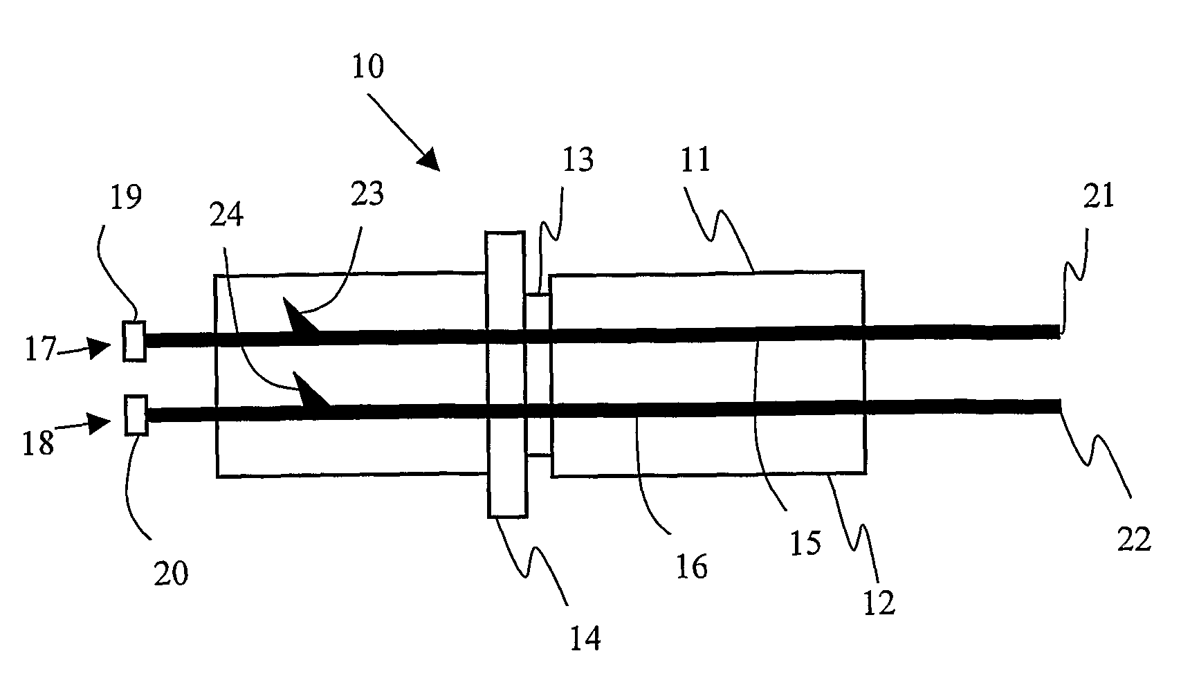
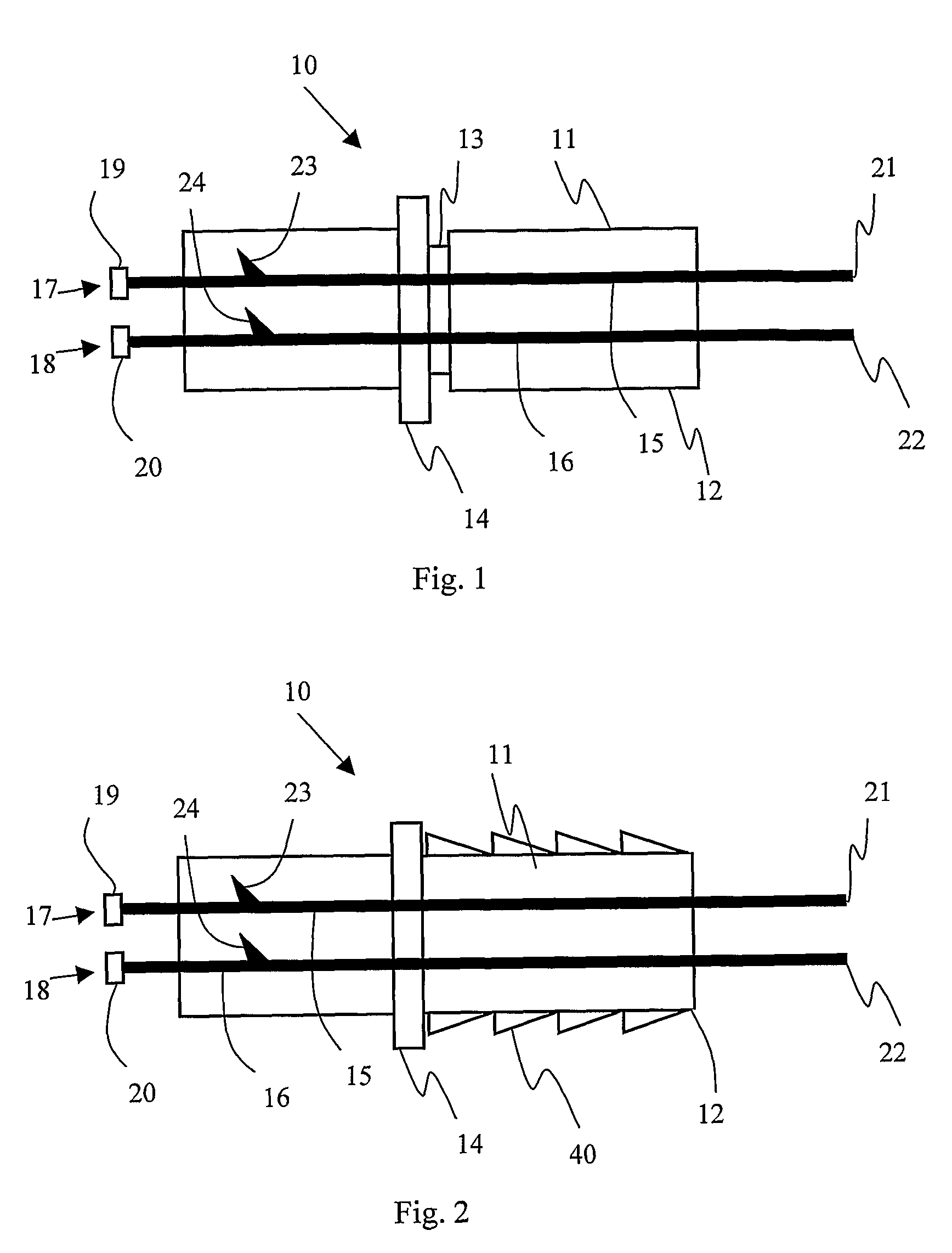
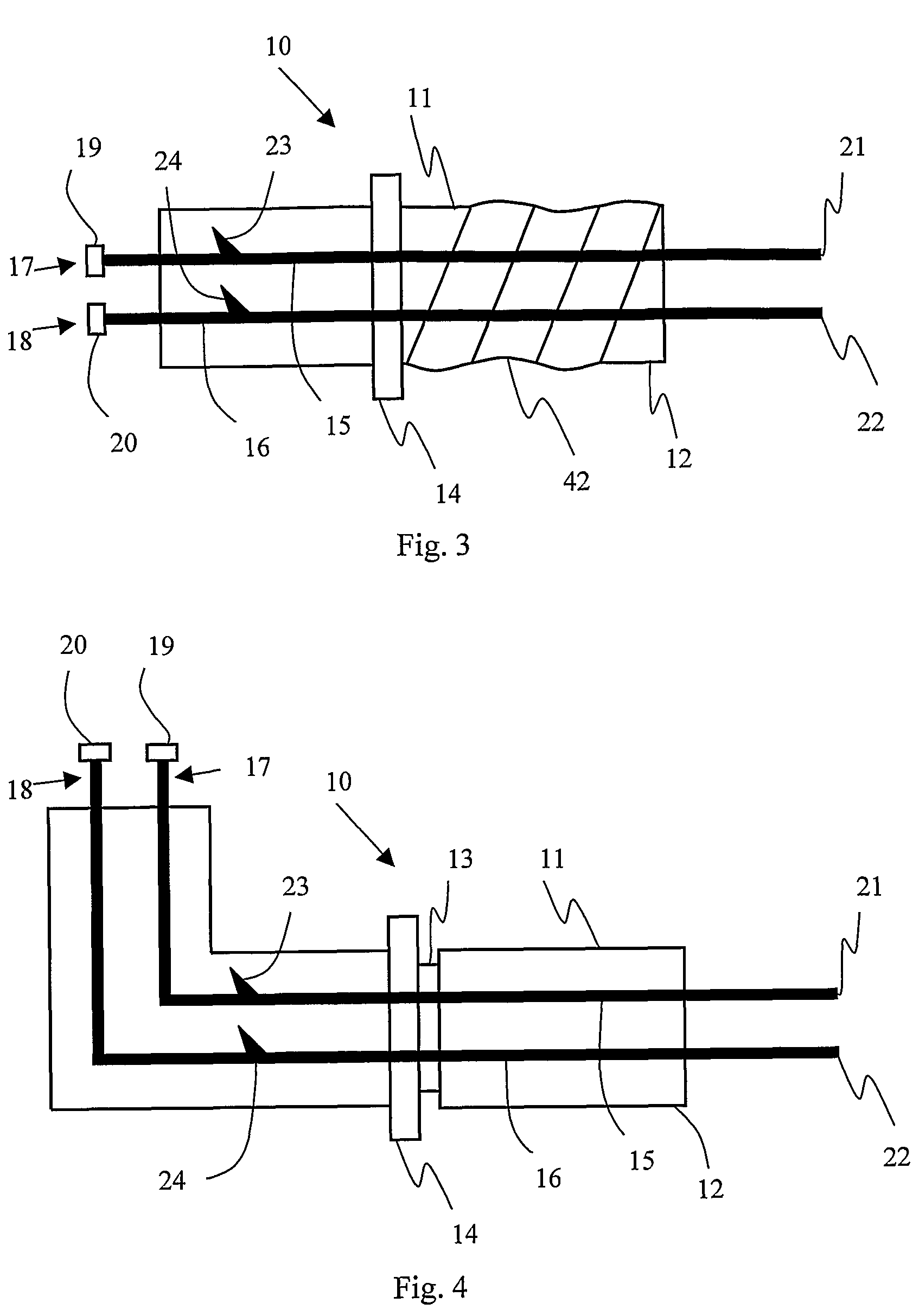
[0077]The present invention provides, at least in preferred embodiments, for an electrical connector for securing a signal transmission line to a detonator, or at least to one or more initiation components of a detonator. Preferably, the connector may form part of a modular-type electronic detonator apparatus, wherein signal transmission lines are connected to electronic detonators at the blasting site, rather then in the factory setting. In this way, the connector of the present invention presents multiple advantages. The principle advantage pertains to the secure connection of the signal transmission line to the electronic detonator, which substantially prevents breakage of the corresponding connections when a tugging or tensile force is applied to the signal transmission line. Preferred embodiments of the invention exhibit further advantages, which include but are not limited to: the suitability of the connector to generate simple modularized detonator systems, and the capacity o...


PUM


Abstract

Fire, arm, and disarm signals are typically transmitted to electronic detonators via signal transmission lines. Traditionally, such signal transmission lines include wires wherein one end of each wire is soldered directly to printed circuit boards and / or other signal processing components retained within the shell of a detonator. Other ‘modular’ blasting apparatuses of the prior art provide means to connect signal transmission lines to detonators in the field. Signal transmission line / detonator contacts are susceptible to disruption, particularly when the signal transmission lines are subject to inadvertent tugging or tensile forces at the blast site. The present application discloses an electrical connector that enables secure connection between a signal transmission line and any detonator adapted to receive and optionally process electrical signals from the signal transmission line. Specifically, the electrical connector can be affixed to the signal input end of a detonator, and includes at least one bridge element to provide electrical contact between a signal transmission line, and internal electrical component(s) of the detonator.

Description

FIELD OF THE INVENTION[0001]The present invention relates to detonators for use in a blasting network. Specifically, the present invention relates to blasting apparatuses comprising detonators configured to receive one or more electrical signals from attached signal transmission lines, and devices for secure physical and electrical connection of the signal transmission lines to detonators.BACKGROUND TO THE INVENTION[0002]Blasting operations frequently trigger a series of explosions in an exact order, with precise timing. For this purpose, blasting apparatuses can employ electronic detonators that may be initiated to fire in response to electrical signals transferred thereto by signal transmission lines. Typically, electronic detonators are positioned as desired to form a blasting array, each being connected to a blasting machine. The blasting machine may communicate directly with a single detonator or multiple detonators in the array via selected signal transmission lines (including...

Claims


Application Information

Patent Timeline
Patent Type & Authority Patents(United States)
IPC IPC(8): F42B3/12F42B3/26F42B3/103H01R13/41H01R13/58
CPCF42B3/103F42B3/26H01R13/41H01R13/585H01R13/6392F42B3/12
Inventor HUMMEL, DIRKBOOS, THOMAS
Owner ORICA EXPLOSIVES TECH PTY LTD
Why Eureka
Try Eureka