
Kinetic flame device

a technology of kinetic flame and flame support, which is applied in the direction of lighting and heating equipment, lighting support devices, fixed installations, etc., can solve the problems of difficult to provide a convincing simulation that appears real or natural to a viewer, combustion-based candles create safety problems in many environments, and the difficulty of a single candle flame simulation, etc., to achieve the effect of reducing control and/or driving requirements or components

Active Publication Date: 2011-12-06
L&L CANDLE CO LLC
View PDF55 Cites 171 Cited by
  • Summary
  • Abstract
  • Description
  • Claims
  • Application Information

AI Technical Summary

Benefits of technology

The device produces a convincing and realistic simulation of a flickering flame with reduced maintenance and energy requirements, adaptable to various form factors and applications, while maintaining a robust and long-lasting design.

Problems solved by technology

A difficult challenge for a special effects artist is the simulation of a single candle flame.
Despite the complexity, people are so familiar with the appearance of natural flames that it is very difficult to provide a convincing simulation that appears real or natural to a viewer, especially at short viewing distances of several feet or less.
Combustion-based candles create safety issues in many environments because of the presence of flame and heat.
These conventional candles are high-maintenance and, so, are not suitable for long-term usage such as in religious buildings, theme parks, memorials, window displays, museums, and the like without continuous maintenance.
These and other attempts result in flame displays that are relatively poor imitations of a real flame and have not been widely adopted by the commercial or retail markets.
In addition, such devices typically require substantial energy inputs and require frequent battery replacement, which can drive up purchase and operating costs and require undesirable levels of maintenance for ongoing use.

Method used


Image

  • Kinetic flame device
  • Kinetic flame device
  • Kinetic flame device

Examples


embodiment 300

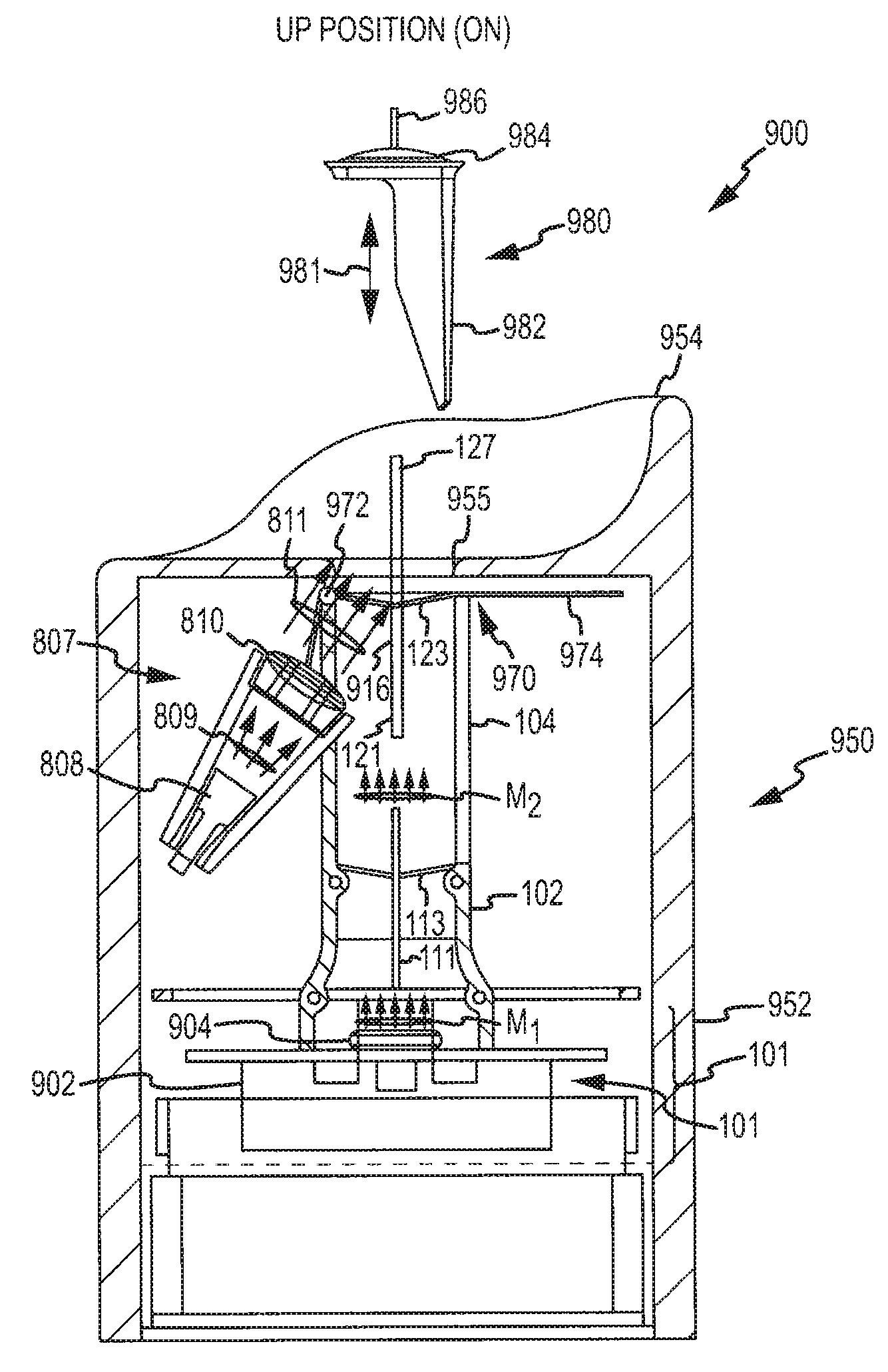
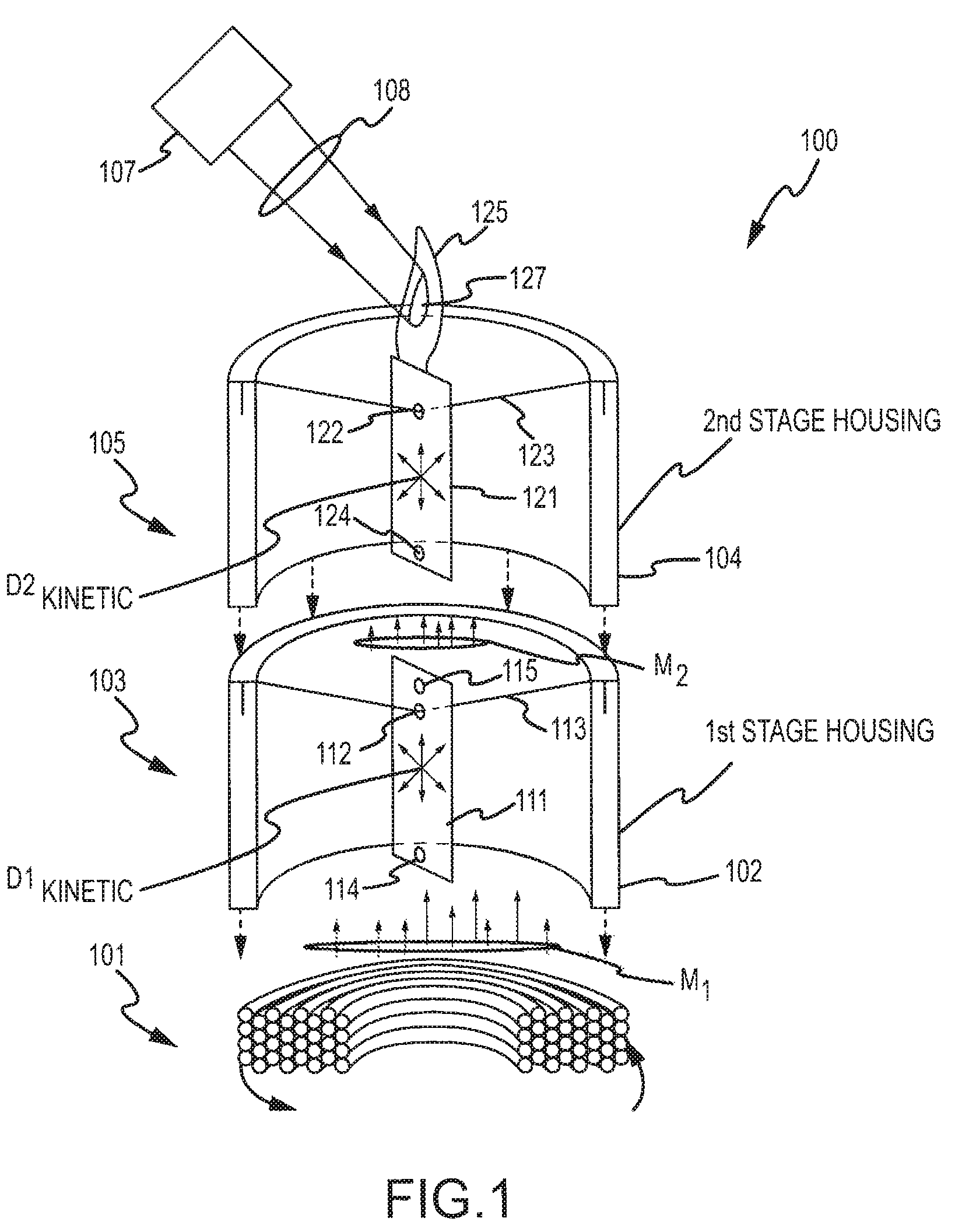
[0052]FIG. 3 and FIG. 4 show an alternative embodiment of kinematic flame device 300 in which a mechanism in accordance with the present invention is embodied in a form factor that is compatible with standard light fixtures with standard light sockets. As such, the embodiment 300 shown in FIG. 3 and FIG. 4 enables a screw-in replacement for conventional bulbs that transforms a conventional lighting fixture into a bulb or device with a flickering candle-like flame appearance. FIG. 3 and FIG. 4 show the same embodiment of device 300 from perspectives that differ approximately orthogonally. Like numbered elements correspond to similar elements in the two figures. In general, the materials, construction and operation of the embodiment shown in FIG. 3 and FIG. 4 are analogous to that described in reference to the stand-alone candle implementation of FIG. 1 (e.g., with interaction of magnets and an electrically generated magnetic field used to create a first kinematic motion / displacement ...

embodiment 500

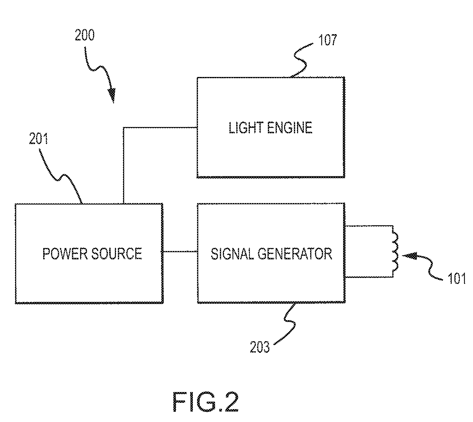
[0058]Devices to implement the functionality of power source 201 and signal generator 203 may be embedded in base 505 in some embodiments, e.g., to selectively generate driving magnetic field, M1. A typical embodiment 500 in accordance with the invention uses low power as compared to conventional light bulbs, and the components necessary to implement that functionality can be very small and readily assembled within or integrated with base 505 and coupled to drive coil 501. First stage pendulum 511 moves about a pendulum support 512 extending through hole 513 to pivotally mount or support pendulum 511. The pendulum 511 has a first or “lower” magnet 514 and a second or “upper” magnet 515 that are analogous in position, function, composition, and construction to lower magnet 114 and upper magnet 115 described in reference to FIG. 1, e.g., first magnet 514 interacts with magnetic field, M1, to create kinetic displacement or motion, D1Kinetic, of pendulum 511. Operation of pendulum 511 i...


PUM


Abstract

An apparatus creating a flickering flame effect. The apparatus includes a housing with an interior space with first and second stages. A drive mechanism generates a time varying electromagnetic field extending into the first stage. A first pendulum member is pivotally mounted in the interior space of the first stage and includes first and second magnets on first and second ends, with the first end proximate to the drive mechanism such that the first magnet interacts with the varying electromagnetic field to cause movement of the pendulum member. The apparatus includes a second pendulum member pivotally mounted in the second stage with a magnet on a first end proximate to the second end of the first pendulum member. A flame silhouette element extends from the second pendulum member, and a light source transmits light onto the flame silhouette, which is moving due to the magnetic coupling of the pendulum members.

Description

CROSS-REFERENCE TO RELATED APPLICATIONS[0001]This application is a continuation-in-part of U.S. patent application Ser. No. 12 / 506,460, filed Jul. 21, 2009, and this application also claims the benefit of U.S. Provisional Application No. 61 / 101,611, filed Sep. 30, 2008, both of which are incorporated herein by reference in their entireties.BACKGROUND[0002]1. Field of the Description[0003]The present description relates, in general, to methods and systems for animated lighting, and, more particularly, to systems, devices, and methods for simulating a flickering flame providing kinetic light movement.[0004]2. Relevant Background[0005]A difficult challenge for a special effects artist is the simulation of a single candle flame. Simulated flames in large fires such as fireplaces or stage sets are comparatively easy to design because they are normally viewed from a distance, and much of the effect of a large fire involves glow and embers, which can be readily simulated. A single candle, ...

Claims


Application Information

Patent Timeline
Patent Type & Authority Patents(United States)
IPC IPC(8): F21V33/00
CPCF21S10/04H01K7/06F21W2121/00F21K9/23F21Y2115/10Y10S362/81
Inventor SCHNUCKLE, GARY W.PATTON, DOUGLAS M.
Owner L&L CANDLE CO LLC
Learn More