Method for manufacturing dielectric isolation type semiconductor device
a dielectric isolation and semiconductor technology, applied in the direction of semiconductor devices, electrical appliances, transistors, etc., can solve the problems of semiconductor substrate warpage, and achieve the effect of preventing the warping of the semiconductor substrate and improving the resistance to voltag
- Summary
- Abstract
- Description
- Claims
- Application Information
AI Technical Summary
Benefits of technology
Problems solved by technology
Method used
Image
Examples
first embodiment
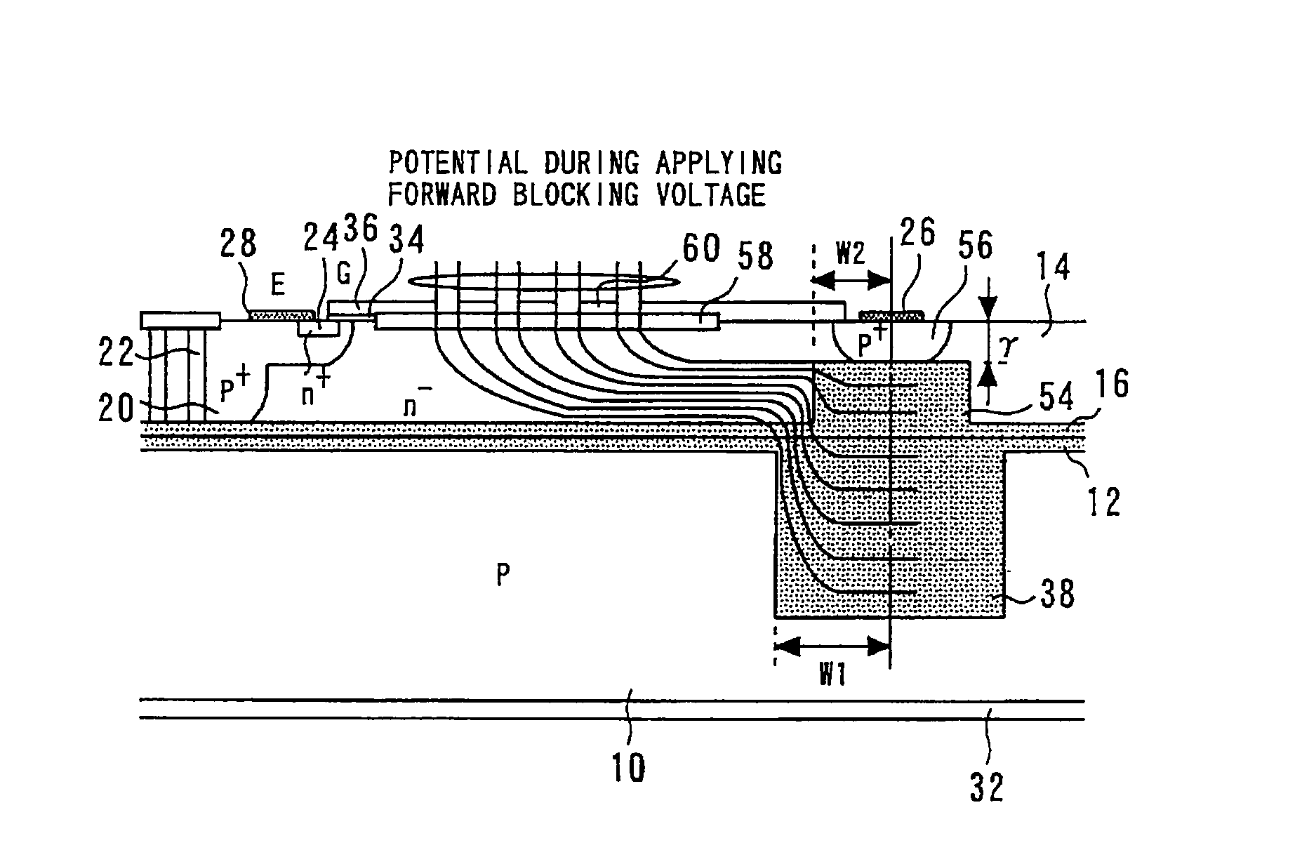
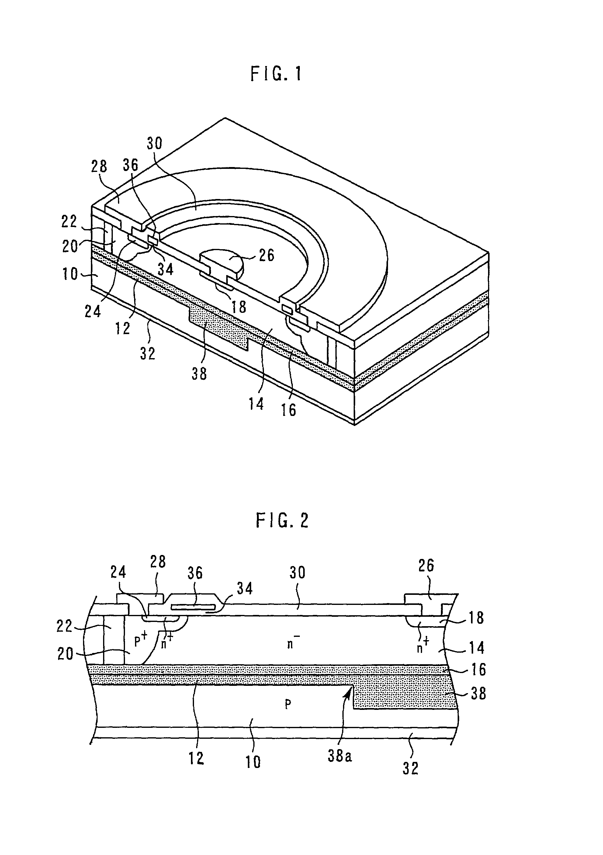
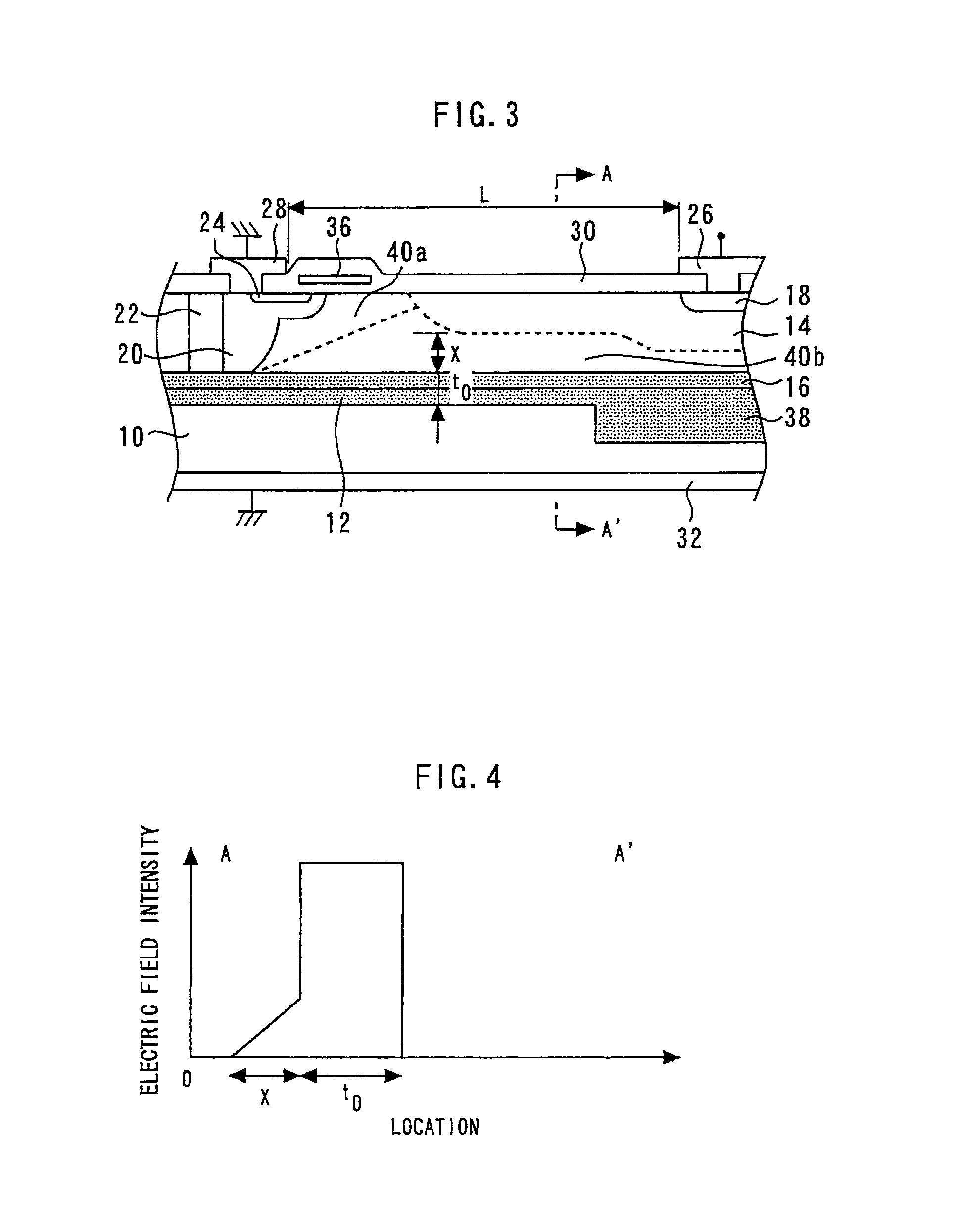
[0024]FIG. 1 is a sectional perspective view showing a dielectric isolation type semiconductor device according to the first embodiment; and FIG. 2 is a sectional view showing the main part of the dielectric isolation type semiconductor device according to the first embodiment.
[0025]A dielectric layer 12 is formed on the major surface of a p-type silicon substrate 10. A dielectric layer 16 is formed on the major surface of an n−-type semiconductor layer 14. The dielectric layer 12 and the dielectric layer 16 are tightly joined, and the n−-type semiconductor layer 14 is bonded to the major surface of a p-type silicon substrate 10. The dielectric layers 12 and 16 dielectrically separate the p-type silicon substrate 10 and the n−-type semiconductor layer 14.
[0026]An n′-type semiconductor region 18 having a higher impurity concentration than the n−-type semiconductor layer 14 is selectively formed on the surface of the n−-type semiconductor layer 14. A p+-type semiconductor region 20 is...
second embodiment
[0049]A method for manufacturing a dielectric isolation type semiconductor device according to the second embodiment will be described. The second embodiment differs from the first embodiment in the forming process of trenches 44 and the thick dielectric layer 38. FIGS. 12 to 14 are sectional view for illustrating the method for manufacturing the dielectric isolation type semiconductor device according to the second embodiment.
[0050]First, as shown in FIG. 12, a plurality of trenches 44 are formed on the region 42 in the major surface of the p-type silicon substrate 10. Here, the width α of the region between the trenches 44 is made to be smaller than 1 μm, and the opening part β of the trenches 44 is made to be about 1.5×α. Then, boron is rotation-implanted on the entire upper surface of the p-type silicon substrate 10 including the sidewalls and the bottoms of the trenches 44 and heat diffusion is conducted to form a p-type high-concentration diffusion region 46 integrally in the ...
third embodiment
[0055]A method for manufacturing a dielectric isolation type semiconductor device according to the third embodiment will be described. FIGS. 15 to 18 are sectional views for illustrating the method for manufacturing the dielectric isolation type semiconductor device according to the third embodiment.
[0056]First, in the same manner as in the first embodiment, a dielectric layer 12 and a thick dielectric layer 38 are formed on a p-type silicon substrate 10.
[0057]Next, as shown in FIG. 15, a plurality of trenches 52 are formed in the region 50 on the major surface of the n−-type semiconductor layer 14. Then, as shown in FIG. 16, the surface of the n−-type semiconductor layer 14 is oxidized by thermally oxidizing the entire wafer. Thereby, a dielectric layer 16 is formed on the major surface of the n−-type semiconductor layer 14, and a thick dielectric layer 54 is formed in the region 50. Thereafter, the surfaces of the dielectric layer 16 and the thick dielectric layer 54 are planarize...
PUM
 Abstract
Description
Claims
Application Information
 - R&D
- Intellectual Property
- Life Sciences
- Materials
- Tech Scout
- Unparalleled Data Quality
- Higher Quality Content
- 60% Fewer Hallucinations
Browse by: Latest US Patents, China's latest patents, Technical Efficacy Thesaurus, Application Domain, Technology Topic, Popular Technical Reports.
© 2025 PatSnap. All rights reserved.Legal|Privacy policy|Modern Slavery Act Transparency Statement|Sitemap|About US| Contact US: help@patsnap.com


