Method and system of finding a read voltage for a flash memory

a flash memory and optimal reading technology, applied in the field of flash memory, can solve problems such as the possibility of changing the threshold voltage distribution, and achieve the effect of reducing the error bit number

Active Publication Date: 2011-12-06
SKYMEDI CORPORATION
View PDF3 Cites 90 Cited by
  • Summary
  • Abstract
  • Description
  • Claims
  • Application Information

AI Technical Summary

Benefits of technology

[0008]In view of the foregoing, it is an object of the present embodiment to provide a method and system of finding a proper or optimal read voltage for a flash memory in order to minimize the error bit number.

Problems solved by technology

In practice, however, the threshold voltage distribution may probably change after the flash memory has been subjected to a predetermined number of program / erase cycles or / and a predetermined data retention time has elapsed.

Method used


Image

  • Method and system of finding a read voltage for a flash memory
  • Method and system of finding a read voltage for a flash memory
  • Method and system of finding a read voltage for a flash memory

Examples


first embodiment

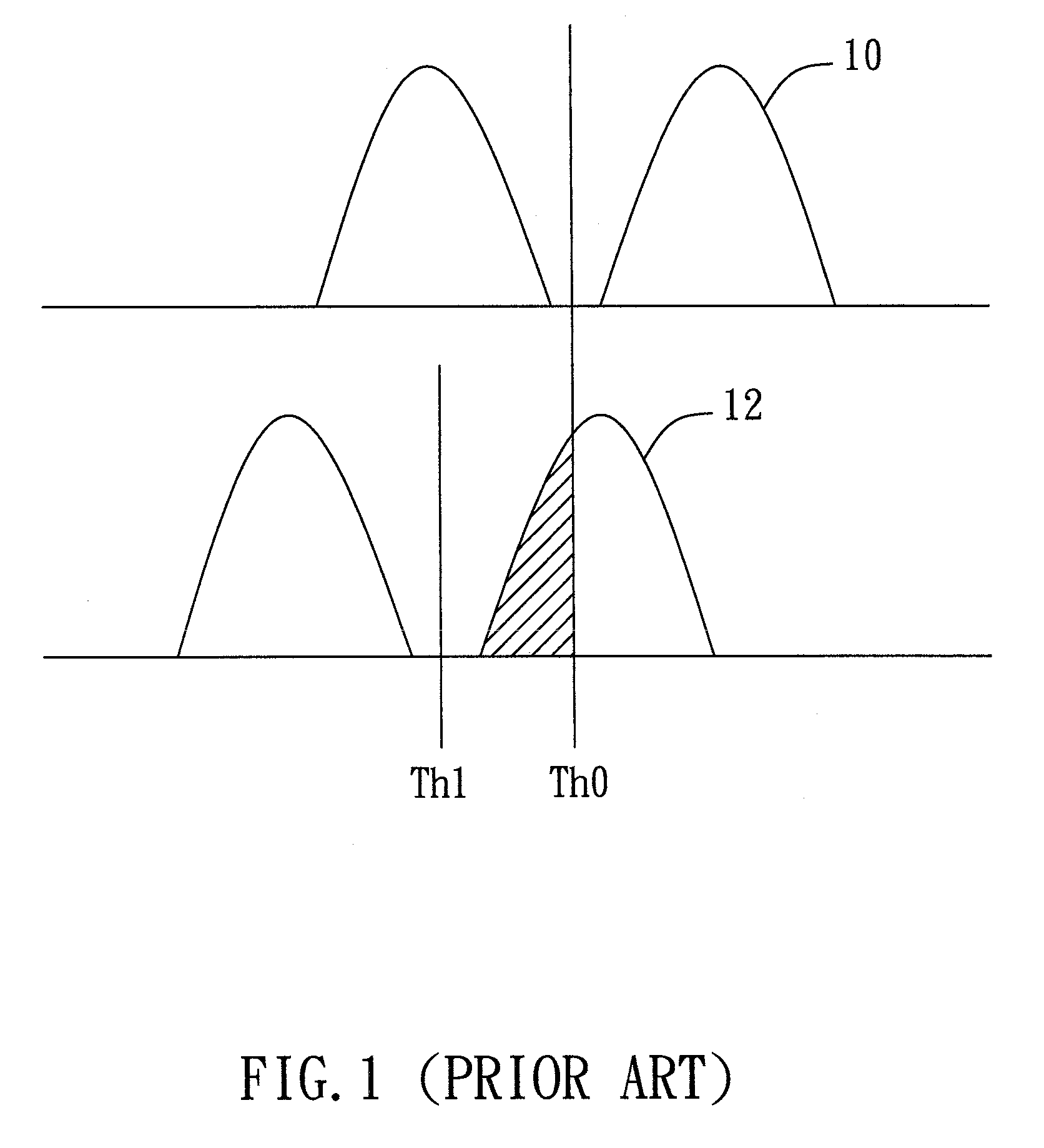
[0026]FIG. 3A shows a detailed flow diagram of the step 24 (of FIG. 2A or FIG. 2B) for determining the optimal read voltage according to the present invention. In the embodiment, a page (or any specific amount) is read from the flash memory many times using multiple read voltages respectively (the step 241). Next, in the step 242, the (cumulative) bit numbers (e.g., N1, N2, etc.) respectively corresponding to the read voltages (e.g., V1, V2, etc.) are counted, for example, as 1,V1>, 2,V2>, etc. Subsequently, in the step 243, an optimal read voltage or offset voltage is determined according to a predetermined lookup table (LUT) that maps a failure ratio (or a failure bit number) to a read voltage (or offset voltage). FIG. 3B illustrates the concept of the failure bit number. As shown in the figure, the recorded (cumulative) bit number of state “1” using a default read voltage V0 is n, and the counted (cumulative) bit number of the state “1” using the read voltage V1 is N1. Therefore,...

second embodiment

[0030]FIG. 4A shows a detailed flow diagram of the step 24 (of FIG. 2A or FIG. 2B) for determining the optimal read voltage according to the present invention. The flow diagram in FIG. 4A is similar to that in FIG. 3A except that the step 243 is now replaced with the step 244, in which the optimal read voltage is determined according to at least two sets of the recorded state bit number (during the programming) and the counted bit number (during the reading). For example, n1 is the recorded bit number for the state “1,” N1 is the first counted bit number for the state “1” using a first read voltage V1, and N2 is the second counted bit number for the state “1” using a second read voltage V2. FIG. 4B shows an example in which the Y axis represents the counted state bit number minus the recorded state bit number, and the X axis represents the associated read voltage. The optimal interpolated read voltage Vtarget between V1 and V2 has a state bit number equal to the counted state bit nu...


PUM


Abstract

A method and system of finding a read voltage for a flash memory is disclosed. Data are read from array cells of the flash memory with a default read voltage, and a recorded state bit number that is recorded during programming is also read. Determine an optimal read voltage if the readout data do not pass the error correction control (ECC). Data are then re-read from the array cells of the flash memory with the determined optimal read voltage.

Description

BACKGROUND OF THE INVENTION[0001]1. Field of the Invention[0002]The present invention generally relates to a flash memory, and more particularly to a method and system of finding an optimal read voltage for a flash memory.[0003]2. Description of the Prior Art[0004]Flash memory is a non-volatile solid state memory device that can be electrically erased and reprogrammed, and is a specific type of electrically erasable programmable read-only memory (EEPROM) device. Conventional flash memory stores a single bit of information in each memory cell such that each memory cell can be programmed to assume two possible states. The conventional flash memory is thus commonly referred to as single-level cell (SLC) flash memory or single-bit cell (SBC) flash memory. Modern flash memory is capable of storing two or more bits of information in each memory cell such that each memory cell can be programmed to assume more than two possible states. The modern flash memory is thus commonly referred to as...

Claims


Application Information

Patent Timeline
Patent Type & Authority Patents(United States)
IPC IPC(8): G11C16/04
CPCG11C11/5642G11C16/34G11C7/1006
Inventor CHOU, MING-HUNGHUANG, CHIEN-FUHUANG, HAN-LUNGCHO, SHIH-KENG
Owner SKYMEDI CORPORATION
Why Eureka
Try Eureka