Conveying duct monitor system for controlling harvester speed

a technology of duct monitor and harvester speed, which is applied in the field of agricultural harvester having air duct system, can solve the problems of typically limited capacity of the cleaner, achieve the effect of reducing the incidence of machine overload or under-capacity operation, facilitating calibration, and maintaining peak machine productivity

Active Publication Date: 2011-12-06
DEERE & CO
View PDF26 Cites 15 Cited by
  • Summary
  • Abstract
  • Description
  • Claims
  • Application Information

AI Technical Summary

Benefits of technology

[0006]It is therefore an object of the present invention to provide an improved system for monitoring a harvester air duct system. It is a further object to provide such a system which overcomes most or all of the aforementioned problems. It is another object of the present invention to provide an improved system for monitoring a harvester air duct system which is reliable, easy to calibrate and unaffected by changes in air pressure in the cab of the harvester. It is yet a further object to provide such a system which helps the harvester operator maintain peak machine productivity and reduces incidences of the machine overload or under-capacity operation.
[0008]One system constructed in accordance with the teachings of the invention utilizes a temperature compensated differential pressure sensor to measure the vacuum in the duct relative to atmospheric pressure or to a positive pressure farther upstream in the duct. This system is the subject of our copending aforementioned U.S. Patent application Ser. No. 10 / 887,963 entitled Conveying Duct Pressure Monitor System for Controlling Harvester Speed, now U.S. Pat. No. 7,249,449. The output from the pressure sensor is monitored electronically and can be displayed and / or used to optimize vehicle speed. In addition, a machine processor monitor output can be used in conjunction with the pressure sensor to control ground speed. Cleaner speed and vacuum in the air duct are monitored to determine which area of the machine is the limiting factor and to adjust harvester speed dependent on that limiting factor. The system is not affected by the variation in cab pressure. Therefore, need for resetting is reduced or eliminated, or achieved automatically. Additionally, the system continuously identifies duct vacuum to allow the operator or an automatic speed control system to adjust vehicle ground speed for optimum performance. Loading on a crop processor structure is also monitored to provide a load indication which is used to control harvester ground speed. The system allows an inexperienced person to operate the machine near maximum capacity without plugging and relieves operator stress by automatically controlling the ground speed. The operator does not have to watch the cleaner speed and vacuum as closely and has more time to monitor and control other machine functions.
[0009]In another embodiment of the invention, a sensor such as a microwave sensor monitors the velocity and mass flow of cotton in the lower air duct. As the flow of cotton in the air duct nears maximum capacity, the cotton velocity will decrease and the sensor provides a signal to the controller so that harvester speed will be reduced appropriately. Also, a moisture sensor can be added to the duct to measure the moisture level of the cotton. The inputs of moisture and cotton mass flow can then be combined to determine the percentage capacity of the cleaner. In dry cotton conditions, the capacity of the entire machine will be determined by the air system. In wetter cotton condition, capacity typically is limited by the cleaner. By determining mass flow and moisture content of the crop material in the duct, cleaner loading can be anticipated for faster response time without reliance solely on cleaner shaft speed and loading. Since cotton mass flow and moisture content are known, the controller can vary speed of the cross auger and impeller to even out the flow of cotton within the air duct system in highly variable yield conditions in the field.
[0010]An optical sensor or other crop condition sensor can also be connected to the harvester to provide an indication of crop conditions immediately forward of the row unit or header to anticipate the amount of crop material that will be entering the duct structure. A signal is provided to the operator and / or to the automatic speed control indicating an approaching potential over- or under-capacity condition to quicken harvester speed changes in response to changing crop conditions. The controller can also process the crop condition signal to determine if changing crop conditions require a harvester speed change. The combination of sensed crop material within the duct structure and anticipated crop condition facilitates a highly accurate and responsive control system for avoiding over- and under-capacity conditions both in the duct system and in the crop processor and maintains optimum productivity of the harvester.

Problems solved by technology

In wetter cotton condition, capacity typically is limited by the cleaner.

Method used


Image

  • Conveying duct monitor system for controlling harvester speed
  • Conveying duct monitor system for controlling harvester speed
  • Conveying duct monitor system for controlling harvester speed

Examples


Embodiment Construction

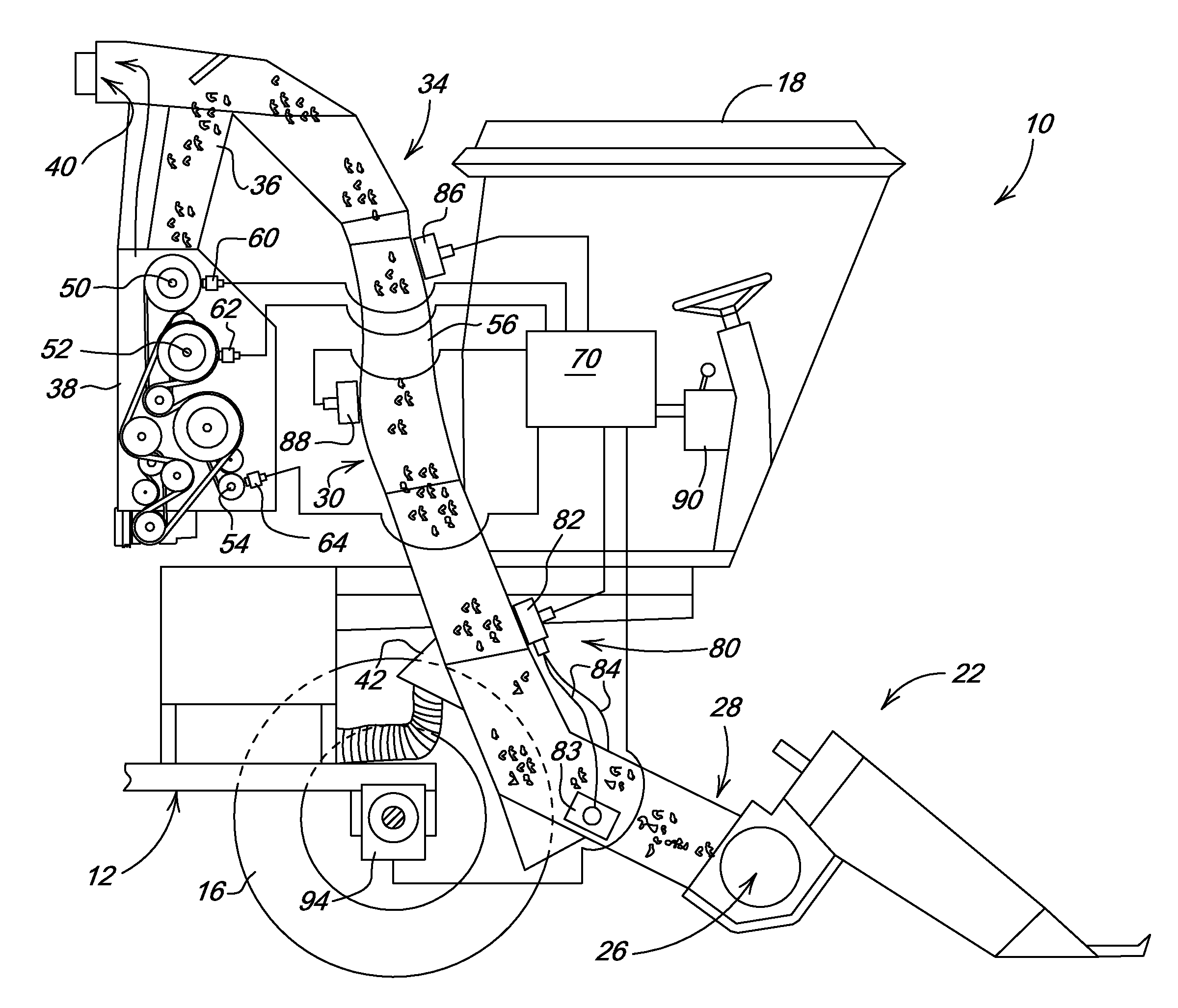
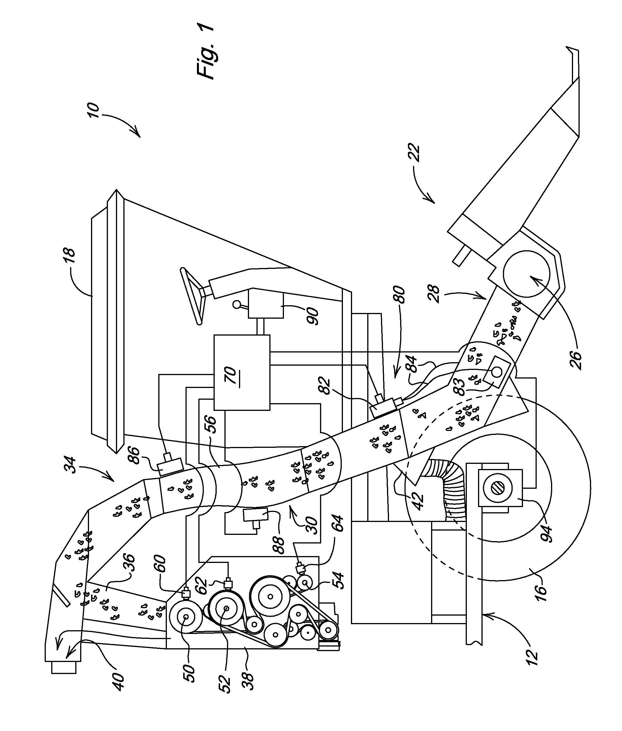
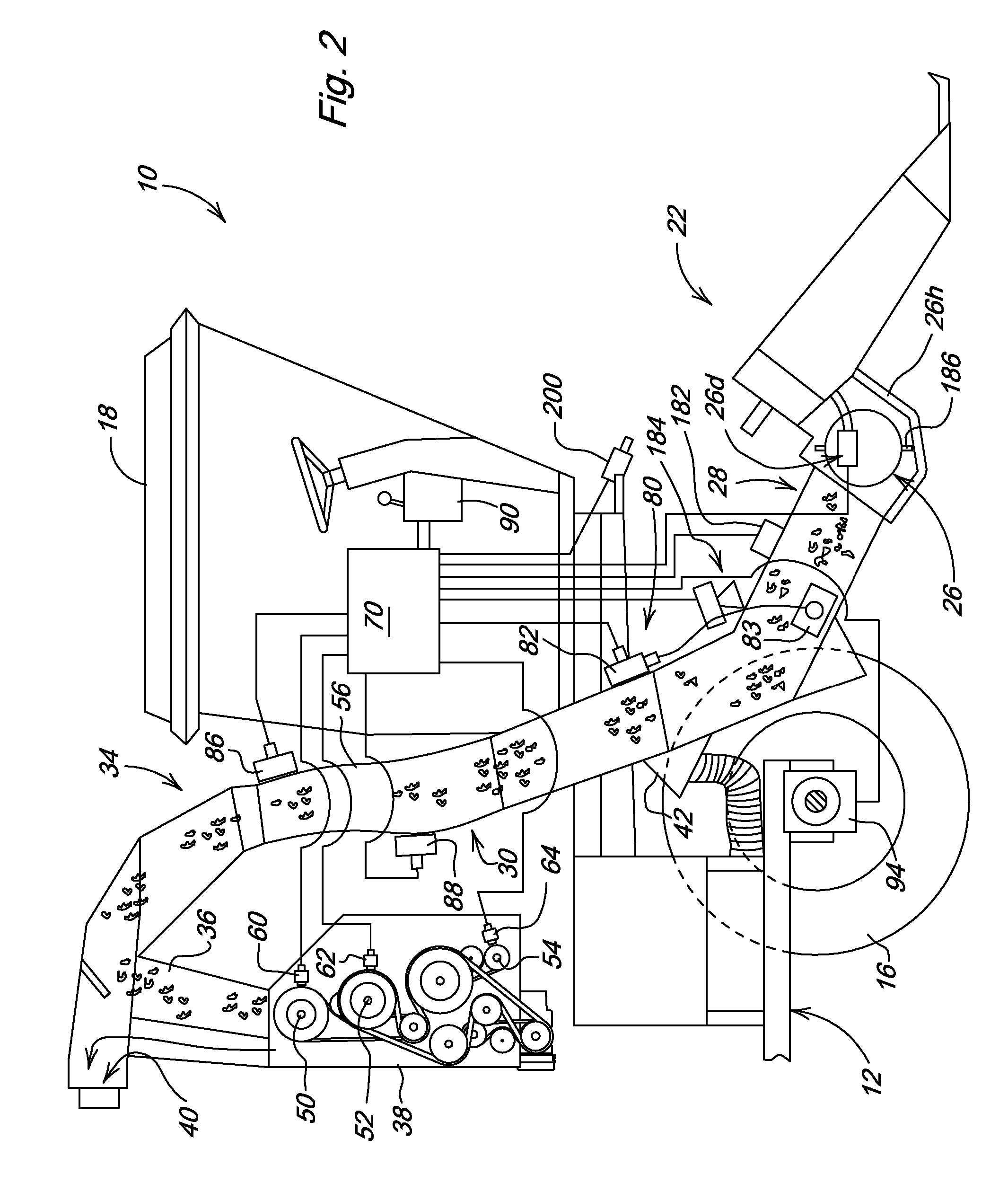
[0014]Referring now to FIG. 1, therein is shown a cotton harvester 10 having a main frame 12 supported for forward movement over the ground by forward drive wheels 16 and rear steerable wheels (not shown). A cab 18 is supported on the forward end of the frame 12. A lift frame is adjustably supported from the forward end of the frame 12 for mounting a conventional header 22 for stripping cotton material from rows of cotton plants. The header 22 includes a cross auger 26 for conveying stripped cotton and other material to a central outlet location which opens rearwardly into a separation duct 28.

[0015]Air duct structure 30 with an S-shaped configuration curves upwardly and rearwardly from the separation duct 28 to an upper separation grate area structure 34 which selectively directs conveyed material downwardly through an input duct 36 to an on-board processor such as a cotton cleaner 38 as shown in FIG. 1, or rearwardly to a basket or receptacle through an outlet area 40. The grate a...


PUM


Abstract

Sensing structure including a microwave sensor monitors the velocity, mass flow and moisture of cotton in a harvester air duct. As the flow of cotton in the air duct nears maximum capacity, the cotton velocity will decrease and the sensor provides a signal to the controller so that harvester speed will be reduced. Cotton mass and moisture level signals are used to determine the percentage capacity and anticipate loading of the cotton cleaner or other crop processor. The signals can also be used to control cross auger and impeller speed to even out the flow of cotton within the air duct system in highly variable yield conditions in the field.

Description

[0001]This application is a continuation in part of, and claims the benefit of priority of, U.S. patent application Ser. No. 10 / 887,963 filed Jul. 9, 2004, assigned to the same assignee as this patent application and entitled Conveying Duct Pressure Monitor System for Controlling Harvester Speed, now U.S. Pat. No. 7,249,449. The contents of that patent application are incorporated herein by reference.FIELD OF THE INVENTION[0002]The present invention relates generally to an agricultural harvester having an air duct system to convey harvested material and, more specifically, to a device for controlling harvester speed dependent on the detected flow in the duct system.BACKGROUND OF THE INVENTION[0003]The harvesting capacity of a cotton harvester is determined by the capacity of the harvesting unit to remove the cotton from the plant and the capacity of the air system to convey the cotton downstream from the harvesting unit. If the harvester is a cotton stripper equipped with a cotton c...

Claims


Application Information

Patent Timeline
Patent Type & Authority Patents(United States)
IPC IPC(8): G06F7/70G06F19/00A01D89/00A01D41/127G06G7/00G06G7/76A01B63/10
CPCA01D46/085A01D46/08
Inventor GOERING, KEVIN JACOBFERREE, PHILIP EUGENEDZUBAK, ALAN LEE
Owner DEERE & CO
Why Eureka
Try Eureka