Metal plate member fixation device installation method

a technology for fixing devices and metal plates, applied in the direction of threaded fasteners, screwdrivers, manufacturing tools, etc., can solve the problems of wasting time and labor, complex mounting and dismounting procedures of moving plate members, and high processing costs, so as to reduce the diameter in direction and the effect of less effor

Active Publication Date: 2011-12-13
WANG KUO CHUNG
View PDF13 Cites 3 Cited by
  • Summary
  • Abstract
  • Description
  • Claims
  • Application Information

AI Technical Summary

Benefits of technology

[0007]The present invention has been accomplished under the circumstances in view. It is therefore an object of the present invention to provide a metal plate member fixation device installation method, which facilitates mounting and dismounting of a metal plate member fixation device and assures high durability of the metal plate member fixation device.
[0011]Further, the screw member comprises an operating portion protruded from the head thereof and a tool groove defined in the operating portion for enabling the screw member to be rotated by a hand tool. Further, the cap comprises an embossed grip formed integral with the periphery thereof, a tapered bottom coupling flange surrounding the center opening and gradually reducing in diameter in direction away from the embossed grip, and a plurality of longitudinal crevices equiangularly spaced around the tapered bottom coupling flange, facilitating coupling of the cap to the barrel. Further, the tool groove can be a Phillipes groove, keystone groove, asterisk groove or hex groove so that a corresponding screwdriver or wrench can be used to rotate the screw member with less effort.

Problems solved by technology

This movable plate member mounting and dismounting procedure is complicated, wasting much time and labor.
This processing process requires high precision and wastes time and labor.
During processing, the cap may be compressed excessively, resulting in permanent deformation.
However, the plastic cap may be permanently deformed or the structural strength of the plastic cap may be weakened during the reflow soldering process.
Further, the spring member will be tempered during the reflow soldering process, lowering its structural strength and shortening its service life.

Method used


Image

  • Metal plate member fixation device installation method
  • Metal plate member fixation device installation method
  • Metal plate member fixation device installation method

Examples


Embodiment Construction

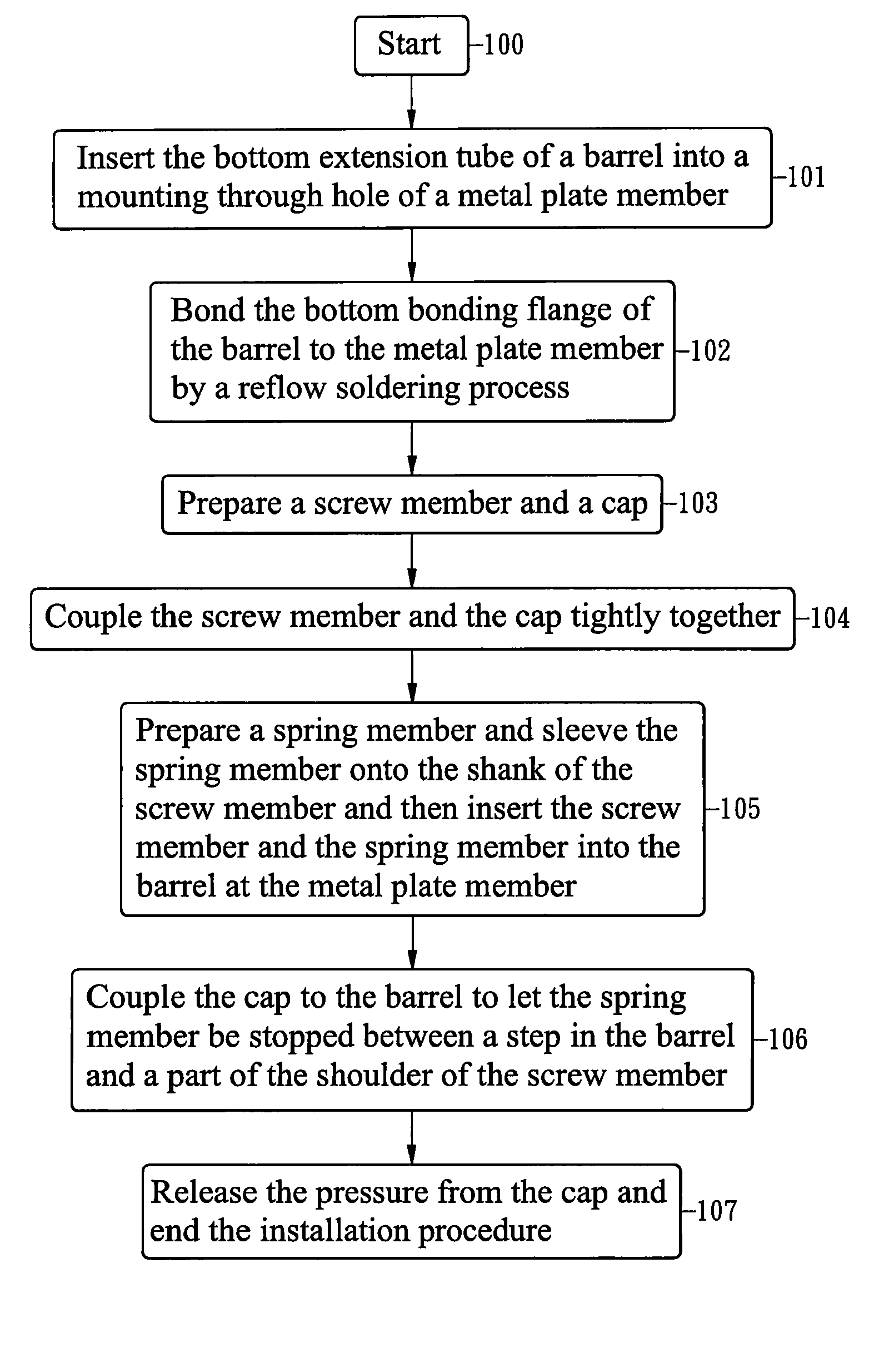
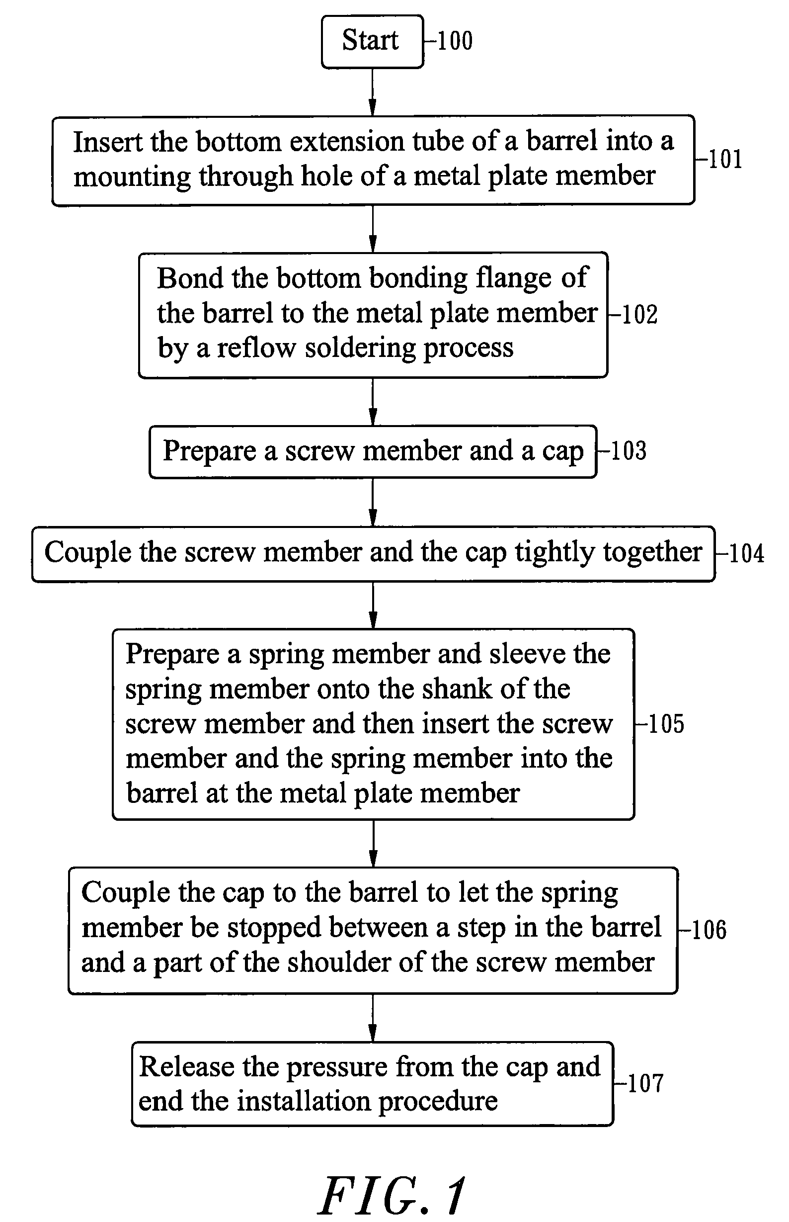
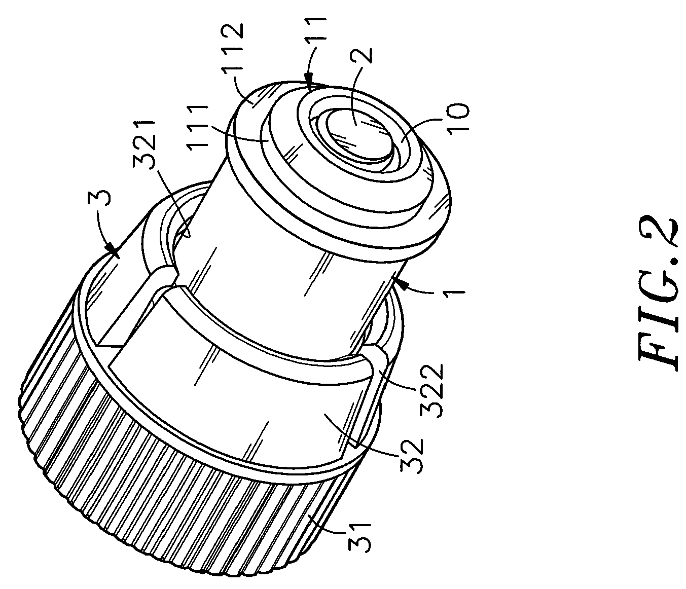
[0021]Referring to FIGS. 1˜5, a metal plate member fixation device installation method in accordance with the present invention includes the following steps:[0022](100) Prepare a barrel 1 that comprises a top coupling flange 12, a bottom mounting unit 11 having a radially extended bottom bonding flange 112 and an axially extended bottom extension tube 111, a stepped axial hole 10 surrounded by the top coupling flange 12 and the bottom mounting unit 11 and a step 101 defined in the stepped axial hole 10, and then start the installation operation;[0023](101) Insert the bottom extension tube 111 of the bottom mounting unit 11 of the barrel 1 into a mounting through hole 50 of a first one of two metal plate members 5 to be affixed;[0024](102) Keep inserting the bottom extension tube 111 of the bottom mounting unit 11 of the barrel 1 into the mounting through hole 50 of the first one of the two metal plate members 5 to abut the bottom bonding flange 112 of the bottom mounting unit 11 of ...


PUM

PropertyMeasurementUnit
pressureaaaaaaaaaa
angleaaaaaaaaaa
diameteraaaaaaaaaa

Abstract

A metal plate member fixation device installation method includes the step of preparing a barrel, the step of bonding the barrel to one of two metal plate members to be affixed by a reflow soldering process, the step of providing a screw member and a cap and coupling the screw member and the cap tightly together, the step of preparing a spring member and sleeving the spring member onto the shank of the screw member and then inserting the screw member and the spring member into the barrel at the metal plate member, the step of axially slidably coupling the cap to the barrel to let the spring member be stopped between a step in the barrel and a part of the shoulder of the screw member, and the step of releasing the pressure from the cap to finish the installation.

Description

BACKGROUND OF THE INVENTION[0001]1. Field of the Invention[0002]The present invention relates to the application of a metal plate member fixation device for joining two metal plate members and more particularly, to a metal plate member fixation device installation method, which facilitates mounting and dismounting of a metal plate member fixation device, avoiding damage to the structural strength or change of physical properties of the screw member, cap and spring member of the metal plate member fixation device and assuring high durability of the metal plate member fixation device.[0003]2. Description of the Related Art[0004]When fastening plate members together, a positioning screw formed of a knob, a ring and a screw nail is usually used. During installation, the screw nail and the ring are secured to the first plate member, and then the knob is rotated to drive the screw nail into the second plate member, and then a hand tool is used to fasten tight the screw nail, affixing the ...

Claims


Application Information

Patent Timeline
Patent Type & Authority Patents(United States)
IPC IPC(8): B23P11/00F16B39/00
CPCF16B5/0208Y10S411/999Y10T29/49948Y10T29/49826Y10T29/49963Y10T29/49947Y10T29/49968
Inventor WANG, KUO-CHUNG
Owner WANG KUO CHUNG
Why Eureka
Try Eureka