Device for placing a tower crane in weathervaning mode

a technology for tower cranes and weathervanes, applied in the direction of cranes, etc., can solve the problems of uncontrollable rotation of the rotating part, inability to weathervane correctly, and risk of cranes falling off, and achieve the effect of adjusting the braking torque and being easy to transpos

Inactive Publication Date: 2011-12-13
MANITOWOC CRANE GROUP FRANCE
View PDF6 Cites 4 Cited by
  • Summary
  • Abstract
  • Description
  • Claims
  • Application Information

AI Technical Summary

Benefits of technology

[0013]The present invention aims to eliminate these disadvantages, therefore to provide an alternative solution to the problem of the uncontrolled rotation of the rotating part of the crane in the event of disturbed wind, which solution does not require any modification to a mass-produced crane and which can be easily transposed from one construction site to another, and which, moreover, constitutes an appropriate solution for cranes in which the slewing mechanism has only one geared motor unit.
[0014]Accordingly, the subject of the present invention is a mechanism for slewing the rotating part of a tower crane, with a device for placing the tower crane in weathervaning mode, the mechanism comprising at least one slewing geared reduction unit with a motor and reduction gear, and with an internal main brake which is deactivated when the crane is placed out of service, and also additional braking means which can be activated when the crane is placed out of service in order to exert on the rotating part of the crane a braking torque which avoids uncontrolled rotation of said rotating part when placed in weathervaning mode, this slewing mechanism being essentially characterized in that the additional braking means are incorporated in the geared motor unit or in one of the geared motor units in the form of an internal auxiliary brake interposed between the motor and the reduction gear.
[0015]In a preferred embodiment of the invention, the internal auxiliary brake, interposed between the motor and the reduction gear, is a single disk brake controlled by an electromagnet, this brake being supplied electrically so as not to brake the rotation of the rotating part of the crane when the crane is in service, but exerting a braking torque by way of spring means when it is not supplied electrically, thereby avoiding uncontrolled rotation of the rotating part of the crane when it is placed in weathervaning mode.
[0016]Thus, the solution of the invention consists of the addition, within the single geared motor unit or within one of the geared motor units of the slewing mechanism, of an optionally demountable electromechanical assembly composed of a brake, of its electrical box and of its bundle of cables, the device being able to brake an internal shaft of the geared motor unit, and hence to brake the rotating part of the tower crane, while being operational when the crane is placed in weathervaning mode. Conversely, this auxiliary brake must not brake the rotation of the rotating part when the crane is in service, only the main brake coming into play during the operation of the crane. The choice of a single disk brake having electromagnetic control here constitutes a particularly advantageous solution in terms of structural simplicity, space requirement and control.
[0017]Advantageously, the auxiliary brake is designed to exert an adjustable braking torque. In particular, if the brake is a disk brake controlled by an electromagnet and urged in the direction of braking by spring means, these means preferably take the form of compression springs acting axially on an armature disk, the compression of the springs or of certain springs being adjustable by screwing an adjusting ring. Thus, the solution of the present invention can be easily transposed from one construction site to another construction site in which there is also a risk of uncontrolled rotation of the rotating part of the crane, since it allows a straightforward adjustment of the braking torque exerted on this rotating part when the crane is out of service. The device of the invention even allows a use on a construction site where there is no disturbed wind, or without demounting the auxiliary brake, if the braking torque of the auxiliary brake can be adjusted to a zero value, in other words if the springs can be relaxed to such a point that they no longer act on the brake disk.

Problems solved by technology

Thus, the crane does not manage to weathervane correctly, and its rotating part is driven with an uncontrolled rotation.
Under such conditions, there is a risk that the crane might topple over, particularly if a gust of wind strikes the rotating part when said part is oriented perpendicularly to the direction of the wind.
Such disturbed conditions may particularly arise if the crane is installed in an urban site in which neighboring tall buildings exert an influence, or in natural sites such as close to a cliff or in an enclosed valley, or else close to cooling towers of power stations, and other similar situations.
This solution has the disadvantage of being specific to one construction site and to one crane and, since it demands modifications to a crane resulting from mass production, it makes it necessary for the crane to be brought into compliance after work on a construction site has finished.
Moreover, this solution is not suited to the case of a slewing mechanism having a single geared reduction unit, unless there is added to the output of the geared reduction unit an external additional brake which, for its part, requires a significant conversion of the crane.

Method used


Image

  • Device for placing a tower crane in weathervaning mode
  • Device for placing a tower crane in weathervaning mode
  • Device for placing a tower crane in weathervaning mode

Examples


Embodiment Construction

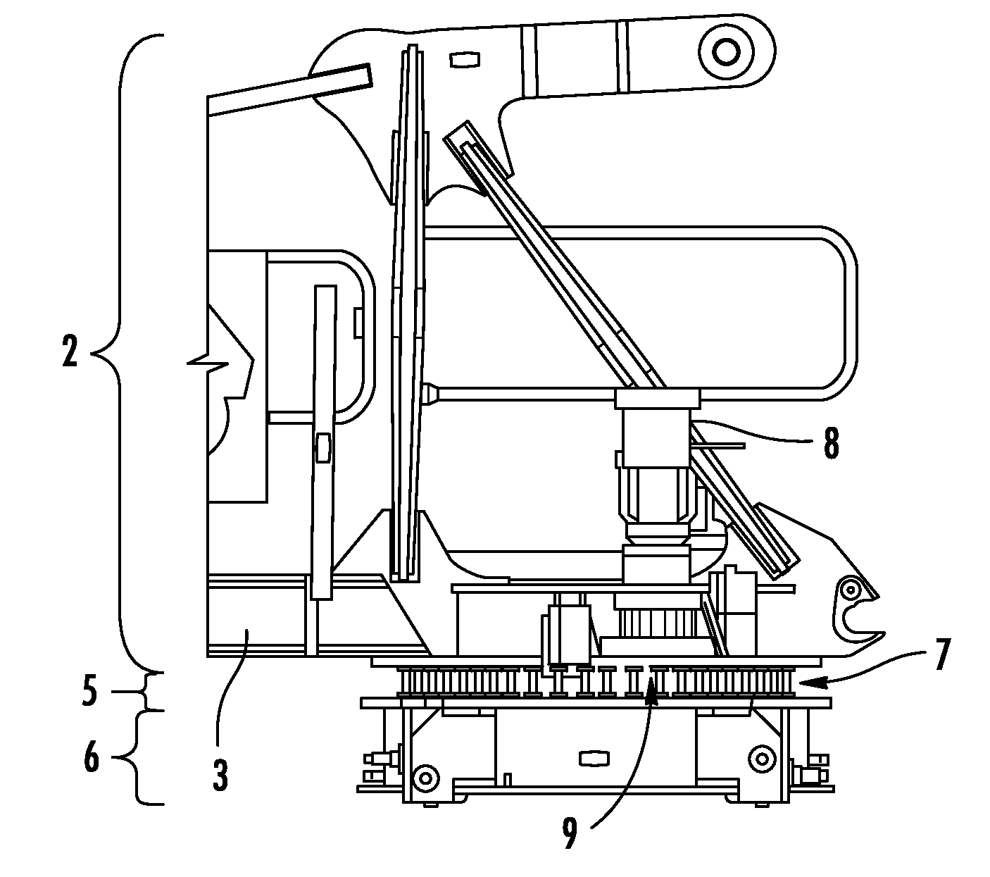
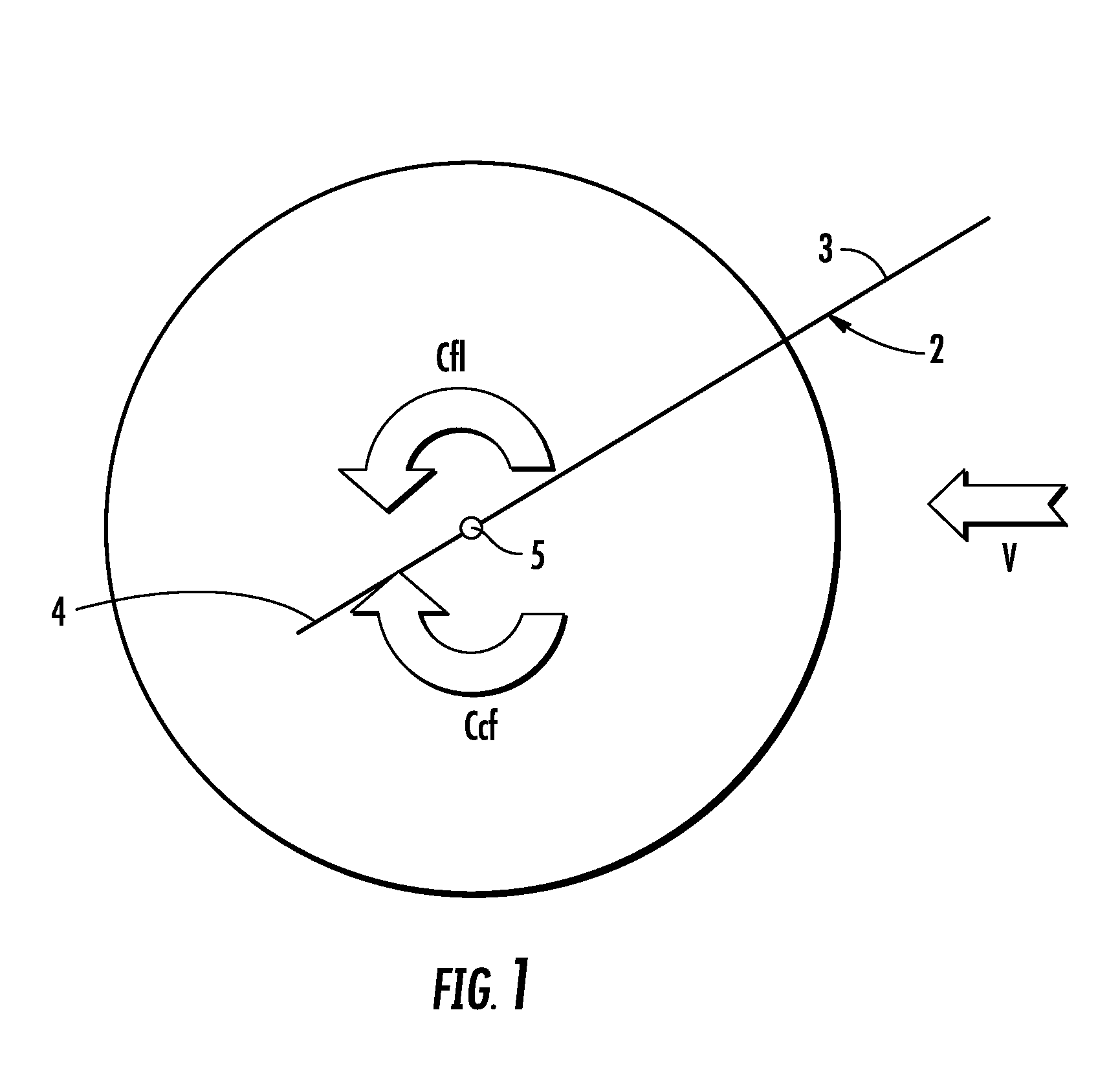
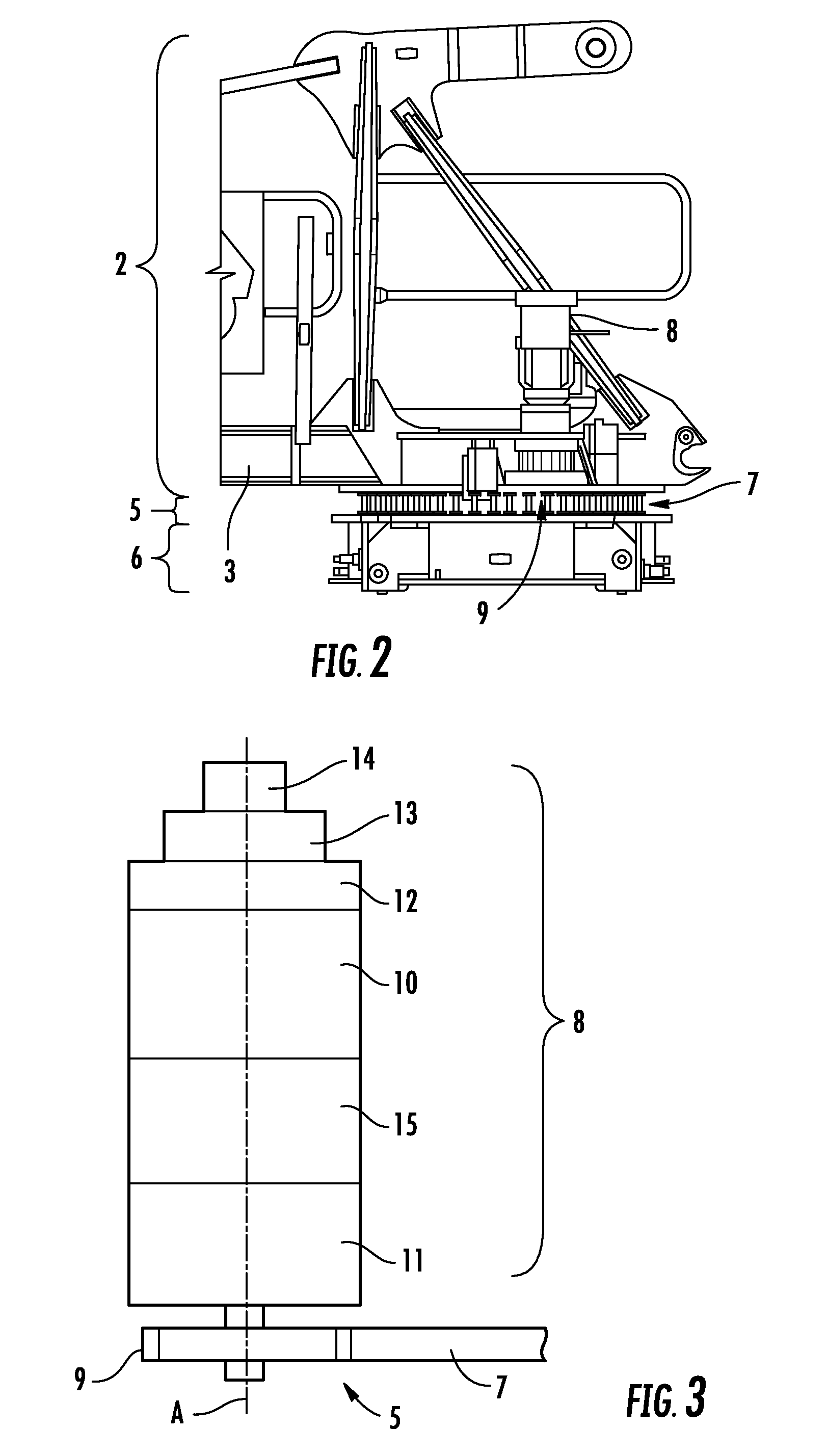
[0023]Referring to FIGS. 1 and 2, the rotating part 2 of a tower crane is composed of a jib 3 and of a counterjib 4, which are aligned on either side of a slewing ring bearing 5 of vertical axis which is mounted on the top 6 of the mast (not shown itself) of the crane. The slewing ring bearing 5 is itself composed of two rings, namely a fixed ring connected to the top 6 of the mast and a movable ring connected to the rotating part 2, the fixed ring externally forming a toothed wheel 7. A geared motor unit 8, which is secured to the rotating part 2, is coupled to a pinion 9, of vertical axis A, which engages with the toothed wheel 7—see also FIG. 3.

[0024]In a known manner, as shown in FIG. 3, the geared motor unit 8 comprises an electric motor 10, a reduction gearset 11 and an internal main brake 12, here placed above the motor 10. Provided above the main brake 12 is a weathervaning device 13, itself surmounted by an encoder 14. The weathervaning device 13 makes it possible to mechan...


PUM


Abstract

The crane includes a rotating part composed of a jib and of a counterjib, and a mechanism for slewing the rotating part that has at least one geared motor unit with a motor and reduction gear, and an internal main brake which is deactivated when the crane is placed out of service, in order to allow the rotating part to slew freely according to the direction of the wind. The geared motor unit also includes an internal auxiliary brake which is interposed between the motor and the reduction gear and which is activated when the crane is placed out of service in order to exert on the rotating part a braking torque which avoids uncontrolled rotation of said part when placed in weathervaning mode. The auxiliary brake can be designed to exert an adjustable braking torque.

Description

TECHNICAL FIELD OF THE INVENTION[0001]The present invention relates, in a general manner, to the technical field of tower cranes. More particularly, this invention relates to the mechanism for slewing the rotating part of a tower crane, and more precisely still to the device for placing the tower crane in weathervaning mode, which device is associated with the slewing mechanism and which, in the case of the present invention, is aimed at facilitating the weathervaning of the crane in a disturbed wind.BRIEF DESCRIPTION OF RELATED ART[0002]A tower crane is conventionally composed of two main parts, firstly a nonrotating vertical pylon, also designated as “mast”, and secondly a rotating upper part, that is to say capable of slewing about a vertical axis of rotation. The rotating upper part, mounted at the top of the mast, is itself composed of a jib, which extends on one side of the vertical axis of rotation of this rotating part, and of a counterjib which is equipped with a ballast an...

Claims


Application Information

Patent Timeline
Patent Type & Authority Patents(United States)
IPC IPC(8): B66C23/94
CPCB66C23/94B66C23/88
Inventor PHILIPPON, PIERRE
Owner MANITOWOC CRANE GROUP FRANCE
Why Eureka
Try Eureka