Damage and leakage barrier in all-composite pressure vessels and storage tanks

a composite wall and barrier technology, applied in the field of pressure vessels, can solve problems such as leakage of pressurized contents, and achieve the effects of reducing leakage, stiffness and strength of the composite wall, and superior barrier against leakag

Active Publication Date: 2011-12-13
COMPOSITE TECH DEV
View PDF38 Cites 32 Cited by
  • Summary
  • Abstract
  • Description
  • Claims
  • Application Information

AI Technical Summary

Benefits of technology

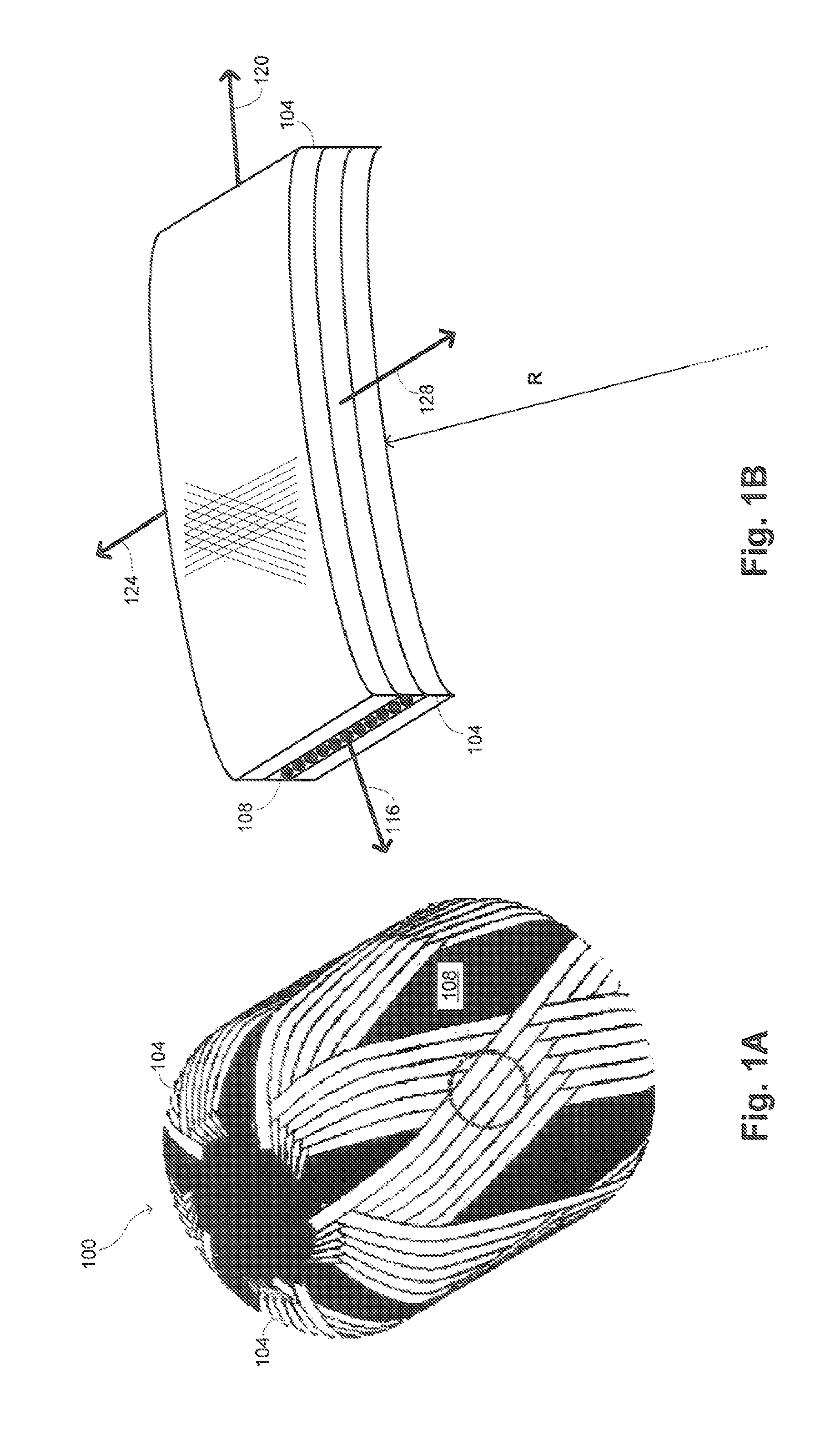
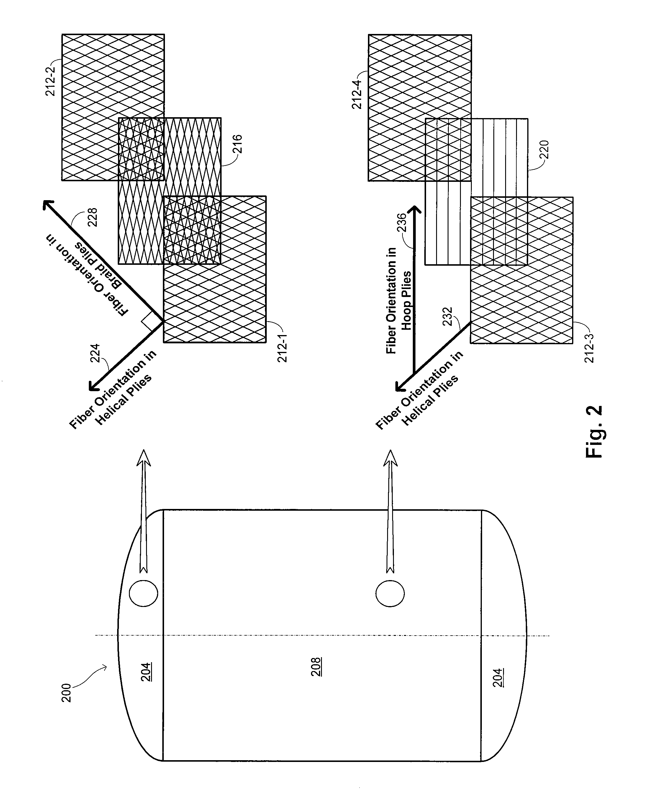
[0010]Embodiments of the invention provide all-composite pressure vessel structures that incorporate the use of braided- or woven-fiber reinforcement and / or highly ductile resin materials in constructing layers (or plies) within the composite wall that provide superior barrier against leakage, while also contributing substantially to the stiffness and strength of the composite wall. Highly ductile resin materials incorporated into either the braided- or woven-fiber plies provide resistance to the initiation of microcracks. The braided- or woven-fiber plies provide a tough protective barrier against the propagation of manufacturing flaws, voids and resin microcracks when a composite pressure vessel is pressurized monotonically or subjected to pressure cycles during service.
[0011]When properly designed into the internal layers of an all-composite pressure vessel, the braided- or woven-fiber plies and / or highly ductile resin materials provide superior barrier performance, which significantly increases the pressure needed to cause a failure by leakage or by rupture in an all-composite pressure vessel. Furthermore, braided- or woven-fiber plies can be designed to exhibit very predictable stiffness and strain-to-failure performance, which can lead to efficient structural load sharing between the barrier plies and the outer structural plies, and highly predictable strain-to-leakage performance in the barrier plies.
[0014]The barrier ply (or plies) may comprise of a braided, woven, filament wound or a combination of fiber arrangements in different embodiments. Braided- or woven-fiber plies provide protection against the propagation of manufacturing flaws, voids and resin microcracks when a composite pressure vessel is pressurized monotonically or subjected to pressure cycles during service, so various embodiments of braided- or woven-fiber plies can result in desirable barrier performance.
[0015]In one embodiment, the braided or woven barrier ply comprises a set of first fibers and a set of second fibers, with each of the second fibers intersecting one or more of the first fibers at an angle that results in uniform, or nearly uniform, tensioning of both sets of fibers in reaction to internal pressurization of the pressure vessel. As internal pressure is increased, the tension forces within the fibers increase nearly uniformly until the burst strength of all fibers is exceeded. This “iso-tensoid” (uniformly tensioned) embodiment of the barrier design is intended to lead to very efficient load-sharing performance between the barrier and non-barrier plies, and uniform failure strength of the barrier in either direction of loading.
[0017]In another embodiment, the braided or woven barrier ply comprises more than two different sets of fibers (e.g., triaxial weave) whose angles and relative tensile-loads can be adjusted to achieve a variety of effects on stiffness and strength performance.
[0018]In another embodiment, the braided or woven barrier ply comprises more than one type of reinforcement (carbon, glass, aramid, Zylon, Spectra, Dyneema etc) or a combination such that the properties can be adjusted to achieve a variety of effects on stiffness and strength performance.

Problems solved by technology

A critical aspect to the design of the barrier ply (or plies) is that its first mode of failure under pressurization is rupture of the fiber reinforcement, confined to the barrier plies, leading to leakage of the pressurized contents.

Method used


Image

  • Damage and leakage barrier in all-composite pressure vessels and storage tanks
  • Damage and leakage barrier in all-composite pressure vessels and storage tanks
  • Damage and leakage barrier in all-composite pressure vessels and storage tanks

Examples


example

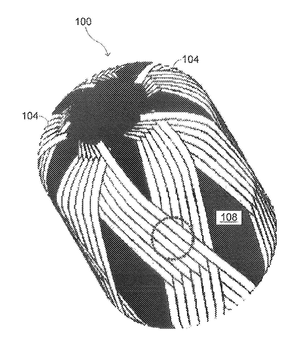
[0057]In one example, a 6 in. dia.×7 in. long, 1.9-L filament-wound linerless pressure vessel was fabricated without any braided ply. The pressure vessel had a weight of 295 grams and failed by leakage, showing a visible spray of water at the knuckle area, at 1000 PSI when subjected to hydrostatic pressure. A comparable pressure vessel with two braided plies interspersed between the normal filament-wound layers throughout the dome regions, but not within the cylindrical region of the pressure vessel had a weight of 315 grams and failed by leakage at 2600 PSI when subjected to hydrostatic pressure. Thus, the inclusion of braided plies selectively in the dome regions that increased the weight by 6.7% provided a performance improvement in excess of 150%.

[0058]In another example, a 6 in. dia.×7 in. long, 1.9-L filament-wound linerless pressure vessel was fabricated in two steps and incorporating barrier plies throughout the pressure vessel. First braided barrier plies were formed, impre...


PUM

PropertyMeasurementUnit
braid angleaaaaaaaaaa

Abstract

A linerless tank structure has a body that defines an enclosed interior volume. The body has a cylindrical section having an axis of symmetry and a dome section coupled with the cylindrical section. The construction of the pressure vessel includes multiple fiber plies. At least one of the fiber plies is a helical ply having fibers traversing the dome helically about the axis of symmetry. At least a second of the fiber plies is a braided or woven ply.

Description

BACKGROUND OF THE INVENTION[0001]This application relates primarily to pressure vessels. More specifically, this application relates to composite-overwrapped pressure vessels and all-composite pressure vessels. This application also relates to composite-overwrapped and all-composite tanks for storage of liquids and / or gases at relatively low pressures.[0002]Pressure vessels and storage tanks find application in a wide assortment of industries. In certain industries, there is a particularly acute need for the pressure vessels to be of light weight. Some examples of these applications include the use of pressure vessels in self-contained breathing apparatus (SCBA) and gaseous fuel storage systems for automobiles, such as storage of compressed natural gas or hydrogen gas. In other applications, lightweight composite pressure vessels and storage tanks may be used on aircraft, launch vehicles, and spacecraft for chemical storage, transport, and / or mixing.[0003]There are a number of diffe...

Claims


Application Information

Patent Timeline
Patent Type & Authority Patents(United States)
IPC IPC(8): F17C1/00F17C1/02B65D8/04B65D1/40B65H81/00B29C53/58F17C1/06
CPCB29C53/602B65D88/06B65D90/022F17C1/06F17C1/16B29C53/8075F17C2201/0109F17C2201/056F17C2201/058F17C2203/0621F17C2203/0665F17C2203/067F17C2203/0673F17C2209/2163F17C2209/232F17C2221/011F17C2221/012F17C2221/031F17C2221/033F17C2223/0123F17C2223/035F17C2223/036F17C2260/011F17C2260/012F17C2260/036F17C2270/0178F17C2270/0184F17C2270/0189F17C2270/0194F17C2270/0781Y02E60/321Y02E60/32
Inventor CRONIN, JOHNMALLICK, KAUSHIKLAKE, MARKWARNER, MARKMUNSHI, NASEEM
Owner COMPOSITE TECH DEV
Why Eureka
Try Eureka