
Bandwidth allocation in a wireless network

a wireless network and bandwidth allocation technology, applied in the field of wireless network bandwidth allocation, can solve the problems of wmns, wmns, and wmns, and achieve the effect of reducing the probability of collision during transmission and ensuring fair bandwidth allocation

Active Publication Date: 2011-12-13
BRITISH TELECOMM PLC
View PDF26 Cites 7 Cited by
  • Summary
  • Abstract
  • Description
  • Claims
  • Application Information

AI Technical Summary

Benefits of technology

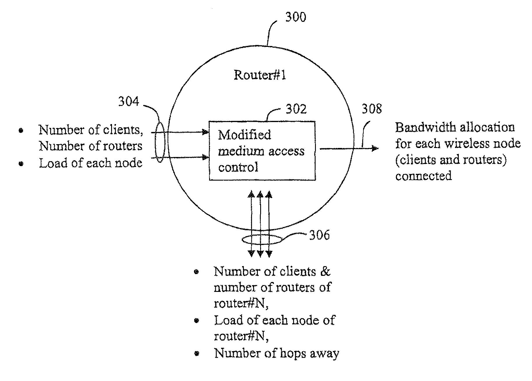
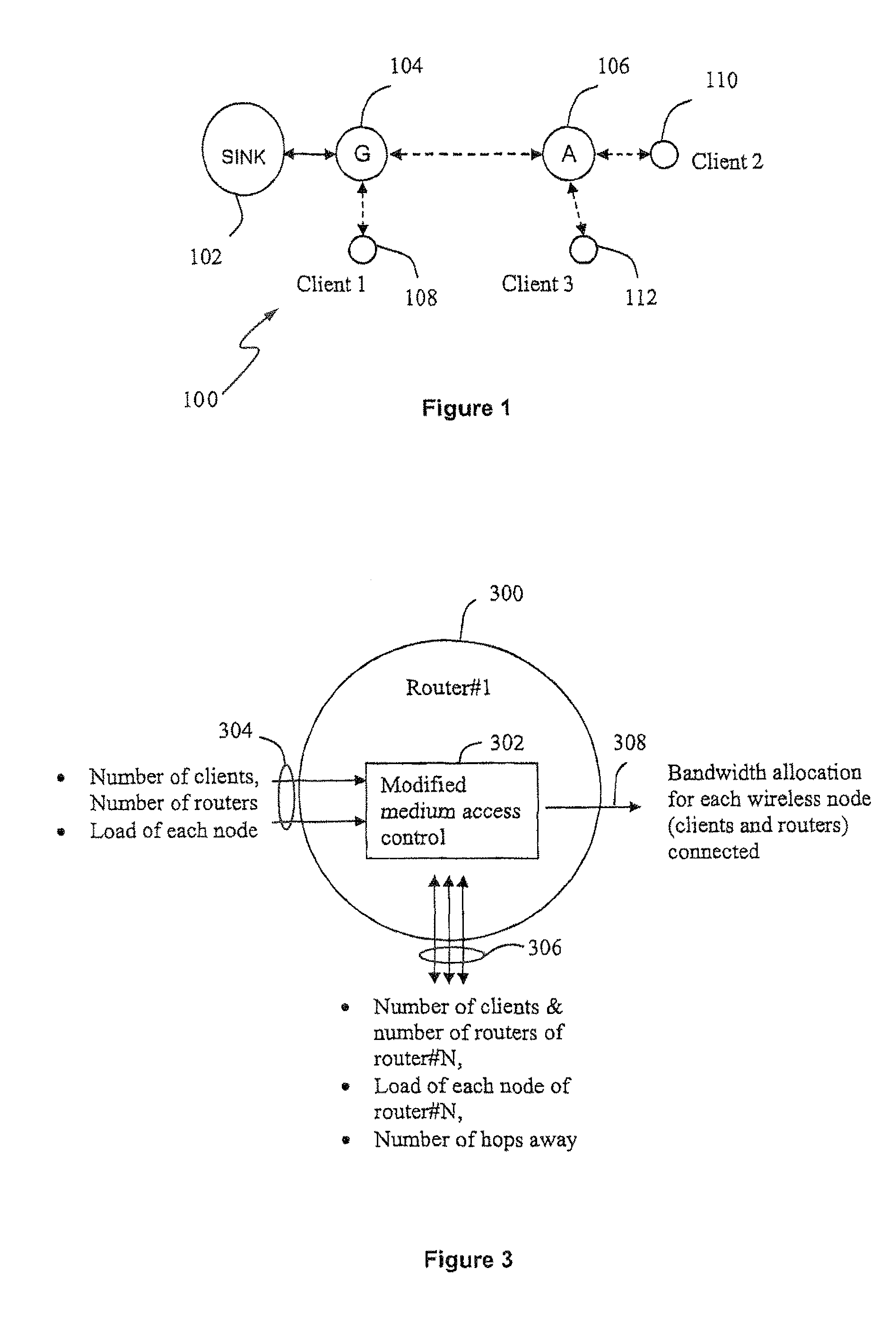
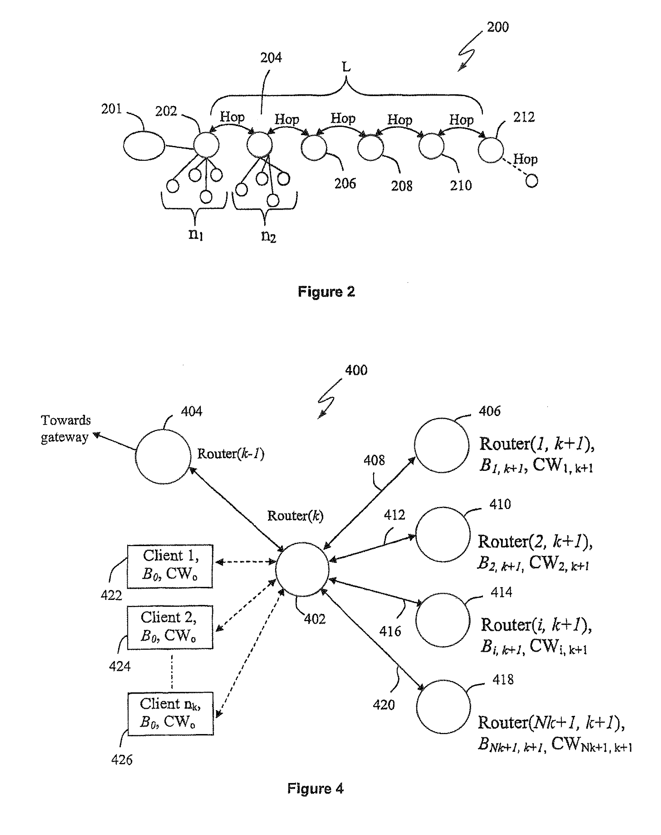
The present invention provides a method for determining a contention window for allocating bandwidth in a wireless network, which takes into account the condition of other nodes in the network. By dynamically altering the contention window based on the condition of its neighbors, the method minimizes the probability of collisions during transmission and allows for a fairer allocation of bandwidth. The method can be easily employed in current networks and provides a compromise between high throughput and fairness. Additionally, the invention provides a wireless network comprising a plurality of nodes, wherein bandwidth is allocated in a fair manner by providing equal access to the wireless medium irrespective of position / location from the gateway.

Problems solved by technology

The routers usually have limited mobility and form the infrastructure or backbone of the WMN.
Both the clients and the routers can organise and configure themselves autonomously to interconnect wirelessly to form the mesh structure, often creating redundant communication paths, which is an inherent characteristic of the mesh topology.
However, problems arise in wireless mesh networks where there are multiple interconnected routers, each with separate clients attached to them.
The problem is therefore to provide a fair allocation of bandwidth across all nodes in a wireless network, irrespective of their physical location in the network.
However, as multihop scenarios are ubiquitous in WMN, the same problem also exists in WMNs.
Therefore, conventional ad-hoc routing protocols cannot efficiently provide a framework for fair distribution of bandwidth in a WMN.
Furthermore, the MAC extension provided by 802.11e for QoS does not cater for this problem.
However, the method is only concerned with bandwidth aggregation between an access point and its clients and does not consider bandwidth aggregation between access points.
Furthermore, the method described does not allocate bandwidth fairly and evenly between all clients.
Furthermore, changes or modifications are only required with the access points or routers and not the clients.
Conventional Wi-Fi network layer protocol using AODV or DSR does not support the exchange of information among the wireless routers / access points for co-ordination in making admission decisions.

Method used


Image

  • Bandwidth allocation in a wireless network
  • Bandwidth allocation in a wireless network
  • Bandwidth allocation in a wireless network

Examples


Embodiment Construction

[0052]The present invention is described herein with reference to particular examples. The invention is not, however, limited to such examples.

[0053]The bandwidth or throughput that a device under 802.11 protocols has depends in part on the ‘contention window’ or ‘back-off window’. The contention window (CW) is part of the waiting period between data frame transmissions at a device, which is used to keep transmissions from colliding with each other. The contention window is divided into consecutively numbered slots, with the number of slots always being 1 less than a power of 2 (e.g. 15, 31, 63, etc). When a node wants to transmit a frame of data, it randomly selects a slot number from the range of (0,CWmin), where CWmin is referred to as the minimum contention window, which is a constant corresponding to the upper limit of the range from which the initial back-off time is selected. The node then counts up to the selected slot number before transmitting the frame. If the node does n...


PUM


Abstract

A contention window for allocating bandwidth in a wireless network is determined. A plurality of nodes includes at least a first and a second router and at least one client connected to each of the first and second routers. Information is received at the first router from the other nodes, the information relating to the condition of the other nodes. A contention window is calculated for the first router based on the received information and the delay is set for a retransmission of data by the first router to the calculated contention window following an unsuccessful transmission of the data.

Description

[0001]This application is the U.S. national phase of International Application No. PCT / GB2006 / 002706 filed 20 Jul. 2006 which designated the U.S. and claims priority to Malaysian Patent Application No. PI20053527 filed 29 Jul. 2005 and European Patent Application No. 05256889.6 filed 7 Nov. 2005, the entire contents of each of which are hereby incorporated by reference.FIELD OF THE INVENTION[0002]This invention relates to a method of allocating bandwidth in a wireless network, in particular a method of fairly allocating bandwidth by dynamically calculating the contention windows used by routers in a wireless mesh network.BACKGROUND TO THE INVENTION[0003]Telecommunications networks are commonplace today and typically operate in accordance with a given standard or specification. These standards ensure interoperability between telecommunications devices and are defined by organisations such as the, Internet Engineering Task Force (IETF), Wireless Ethernet Compatibility Alliance (WECA),...

Claims


Application Information

Patent Timeline
Patent Type & Authority Patents(United States)
IPC IPC(8): H04W4/00G06F15/173H04L45/122H04L47/22H04L47/27H04L47/762H04L47/765
CPCH04L1/1887H04L45/00H04L47/10H04L47/12H04L47/14H04L47/225H04L47/27H04W74/08H04W28/04H04W72/0453H04W84/18H04L1/188H04L12/413H04L12/6418H04L45/20H04L47/762H04L47/765H04L47/822H04L47/824H04L47/826H04W74/002H04W84/12H04W8/04
Inventor MURUGESU, GUKHANSIM, MOH L
Owner BRITISH TELECOMM PLC
Learn More