Keyboard supporting tray and arm rests for conventional open arm office chairs

Active Publication Date: 2011-12-20
MARTIN STEVE
View PDF35 Cites 13 Cited by
  • Summary
  • Abstract
  • Description
  • Claims
  • Application Information

AI Technical Summary

Benefits of technology

[0008]A preferred embodiment includes a tray sized to span a distance between two detachable armrest and support trays mounted in the defined configuration on armrests of a chair for providing additional work area. Preferably, the tray is sized and configured to hold a computer k

Problems solved by technology

Often this arrangement causes a user to hold his wrist in an angled position that has been shown to cause carpal tunnel and other health ailments in users who sit at their computer f

Method used


Image

  • Keyboard supporting tray and arm rests for conventional open arm office chairs
  • Keyboard supporting tray and arm rests for conventional open arm office chairs
  • Keyboard supporting tray and arm rests for conventional open arm office chairs

Examples


first embodiment

[0027]FIG. 5 is a bottom perspective view of the detachable armrest and support tray 11. The detachable armrest and support tray 11 includes a first portion 12 and a second portion 14. The first portion 12 may be attached to an existing armrest using a mount 28 such as clamps, hook and loop fasteners, and any other mount. As seen in FIG. 5, the first portion 12 is held in place by a mount 28. Preferably, the mount 28 includes two mounting bars 15. The bars 15 are sized and configured to fit underneath the first portion 12 between the two downward-extending sides of the portion 12. Screws are inserted through the top 11 into threaded inserts in the mounting bars 15. This allows adjustment for different thickness in armrests.

[0028]To install a detachable armrest and support tray 11, a user places the first portion 12 over an armrest 77, positions the bars 15 underneath the armrest, aligns the screw holes in the ends of the bar with the screw holes in the side of the first portion 12, ...

second embodiment

[0030]FIG. 7 is a perspective view of a detachable armrest and support tray 55 including a molded portion 60 that is attached to the mount 28 in such a way as to allow the molded portion 60 to swivel in relation to the affixed portion 29 so that the detachable armrest and support tray 11 may be stored to the side of a chair while the portion 29 remains attached to an existing armrest. The tray 55 may be attached to the mount 28 by a tether 50. The tether 50 may be a hinge pin, bungee cord, or any other flexible material that allows for two attached items to move in relation to one another. The molded portion 55 may swivel latitudinally and longitudinally in relation to the mount 28 so that the molded portion 60 rests to the side of the mount 28.

[0031]In the view of FIG. 7, the tether 50 is an L-shaped pivot, allowing pivoting about each leg of the L. One leg is in the rear of the portion 29 and the other is in the outside edge of the portion 60. To mount the portion 60 on the portio...

third embodiment

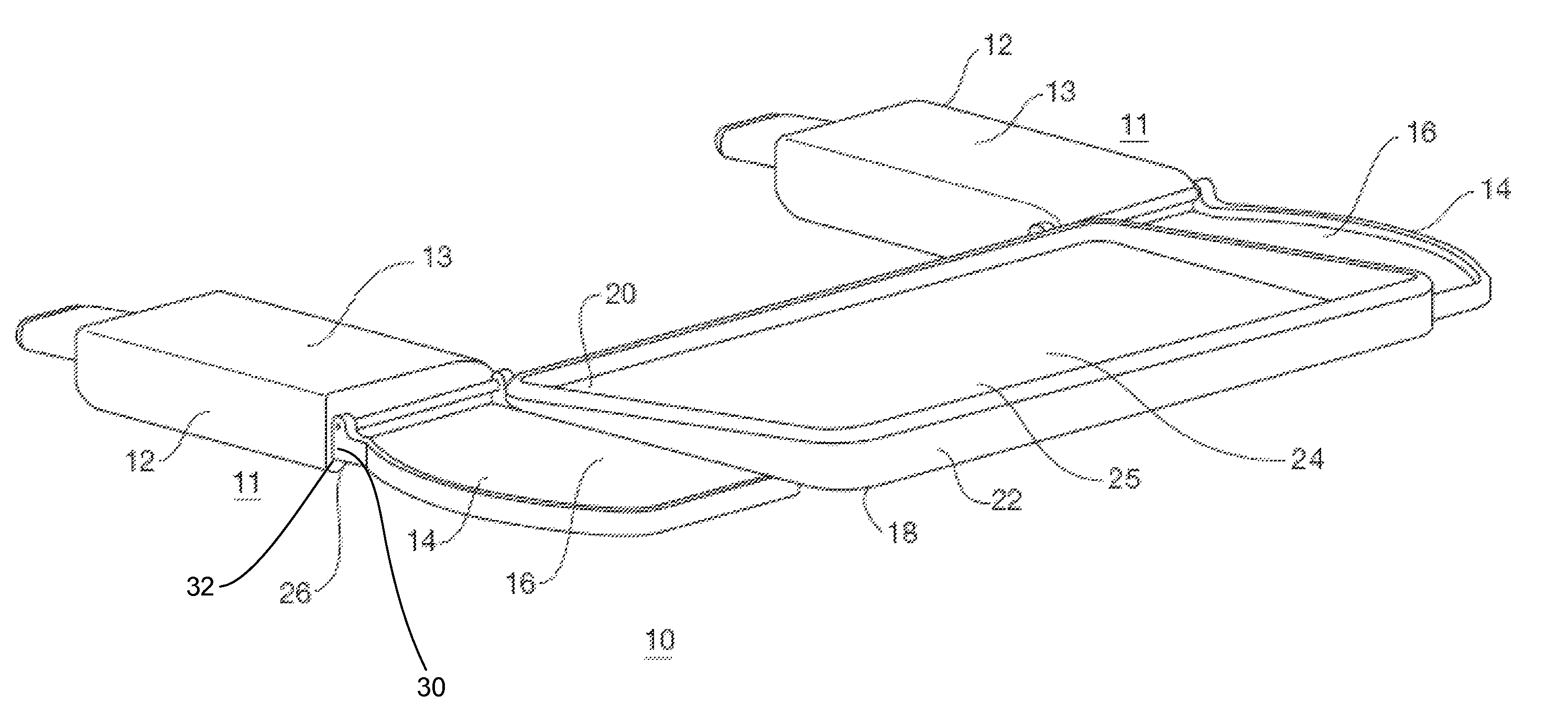
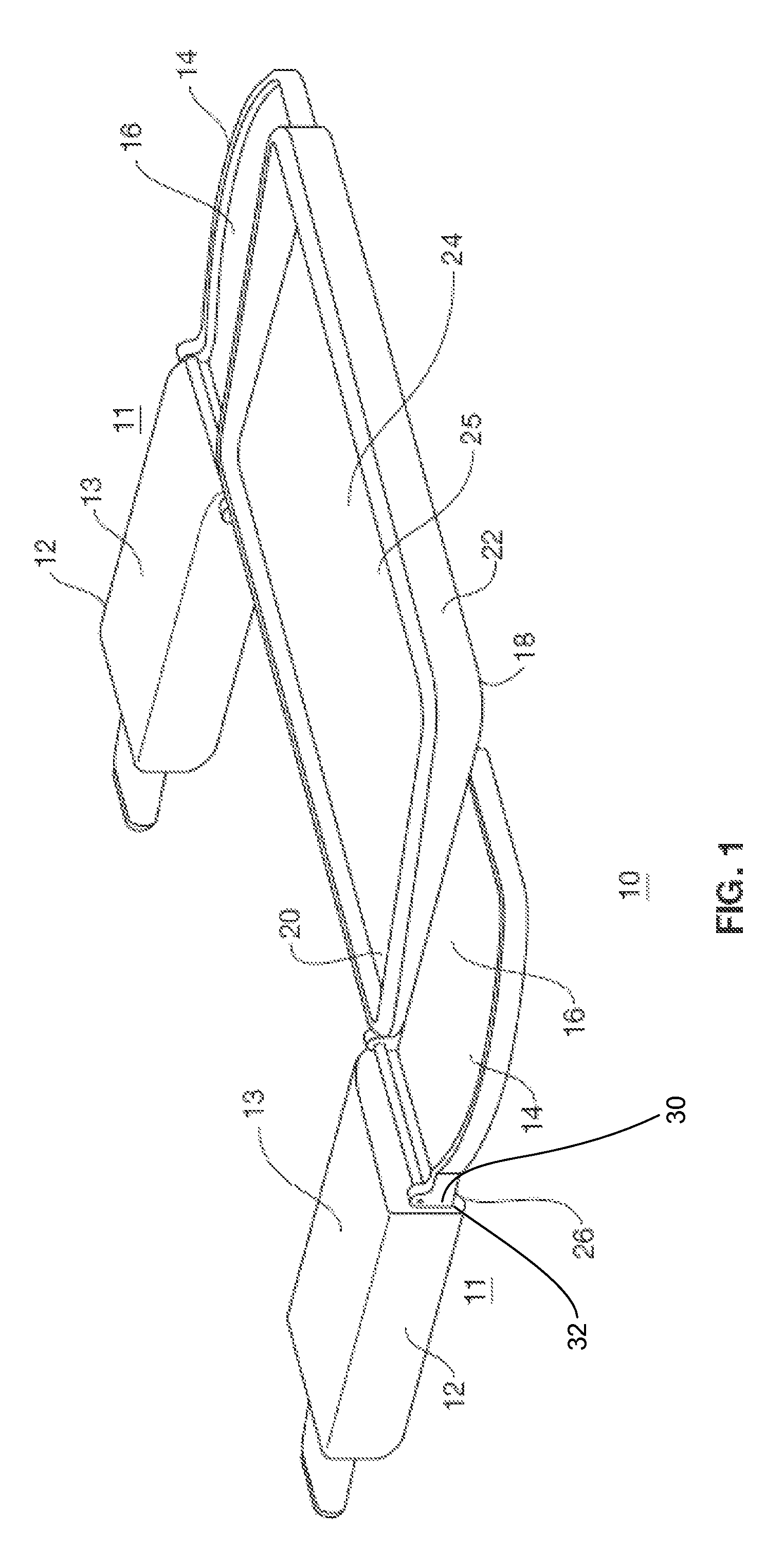
[0032]FIG. 8 is a perspective view of a detachable armrest and support tray 111. The detachable armrest and support tray 111 includes a first portion 112 and a second portion 114 that is pivotally attached to the first portion 112 by a hinge 126 so that the second portion 114 may fold over the second portion 112 for storage. The first portion 112 is attached to the mount 128 by a tether 150 so that the mount 128 may swivel in relation to the mount 128 for storage.

[0033]To store the detachable armrest and support tray 111 a user may fold the second portion 114 over the first portion 112. Then the user may lift the first portion upward, turn the first portion counterclockwise one quarter turn, and then turn the first portion clockwise a half turn.


PUM


Abstract

A peripheral device support assembly. The peripheral device support assembly includes two detachable armrest and support tray adapted to be attached to each arm of an office chair. The detachable armrest and support tray includes a mount for securing the armrest support unit to a chair arm and a first portion hingedly attached to the mount for allowing the first portion to swivel in relation to the mount. The detachable armrest and support tray also includes a second portion pivotally connected to the second portion such that the first portion folds back over a second portion for storage. A tray spans the distance between the second portion of each detachable armrest and support tray to provide additional workspace.

Description

BACKGROUND OF THE INVENTION[0001]The present invention relates generally to ergonomic peripheral device support assemblies, and more specifically to an ergonomic keyboard and mouse pad supporting tray and arm rest for use with conventional open arm office chairs.[0002]The typical computer mouse rests on a desk adjacent a computer monitor. The keyboard may also lie next to the monitor or alternatively may be housed in front of the keyboard. Often this arrangement causes a user to hold his wrist in an angled position that has been shown to cause carpal tunnel and other health ailments in users who sit at their computer for hours at a time.[0003]To alleviate this problem, many users place the keyboard in a pull out tray that is positioned near their lap. However, the mouse is often still at another location. As such, the user must still position his wrist at an awkward angle when using the mouse. In addition, the mouse is not convenient to the keyboard in this position.[0004]Thus there...

Claims


Application Information

Patent Timeline
IPC IPC(8): A47B39/00A47B83/02
CPCA47C7/543A47C7/70Y10S248/918A47C7/705
Inventor MARTIN, STEVE
Owner MARTIN STEVE
Why Eureka
Try Eureka