Fan and impeller thereof

a technology of fan and impeller, which is applied in the direction of liquid fuel engine, vessel construction, marine propulsion, etc., can solve the problems of poor heat dissipation property and loud noise of the fan, and achieve the effect of improving the performance of the fan and reducing the area of the stall region of the fan

Active Publication Date: 2011-12-20
DELTA ELECTRONICS INC
View PDF8 Cites 2 Cited by
  • Summary
  • Abstract
  • Description
  • Claims
  • Application Information

AI Technical Summary

Benefits of technology

[0007]In view of the foregoing, the present invention is to provide an impeller having a plurality of flexible portions for allowing the angle of attack of the blades to be changed according to the load so as to improve the fan property of air pressure and quantity and decrease areas of the stall region.
[0009]As mentioned above, the fan and impeller of the present invention can dynamically change the angle of attack between the blade and the airflow when the impeller rotates. Therefore, the areas of stall region of the fan can be decreased, so that the performance of the fan can be improved.

Problems solved by technology

In this stall period, the airflow worked by the blade is very unstable, which results in loud noise and poor heat dissipation property of the fan.

Method used


Image

  • Fan and impeller thereof
  • Fan and impeller thereof
  • Fan and impeller thereof

Examples


Embodiment Construction

[0016]The present invention will be apparent from the following detailed description, which proceeds with reference to the accompanying drawings, wherein the same references relate to the same elements.

[0017]A fan and an impeller thereof according to an embodiment of the present invention, which can decrease areas of the stall region and improve the fan property of air pressure and quantity, will be described herein below.

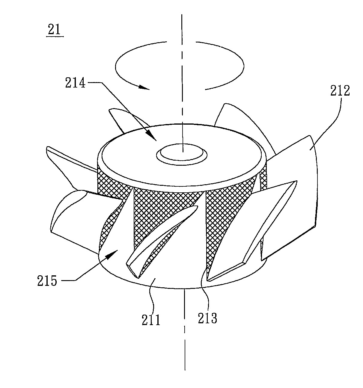
[0018]With reference to FIGS. 3, 4 and 5, a fan 20 according to the preferred embodiment of the present invention includes an impeller 21 and a fan frame 22 accommodating the impeller 21. The impeller 21 includes a hub 211 and a plurality of blades 212 disposed around the hub 211. Several flexible portions 213 are disposed and located on the side wall of the hub 211. The blades 212 are disposed corresponding to the flexible portions 213, respectively, so that the blades 212 can be disposed on the hub 211. The hub 211 includes a top portion 214 and a side wall 215 c...


PUM


Abstract

A fan includes an impeller and a fan frame. The impeller is accommodated within the fan frame. The impeller has a hub and a plurality of blades disposed around the hub. The hub has a top portion and a side wall connected with the top portion. The hub further has a plurality of flexible portions disposed and located on the side wall. The blades are connected with the flexible portions, respectively, so that the blades are connected to the hub.

Description

CROSS REFERENCE TO RELATED APPLICATIONS[0001]This Non-provisional application claims priority under 35 U.S.C. §119(a) on Patent Application No(s). 097111612, filed in Taiwan, Republic of China on Mar. 31, 2008, the entire contents of which are hereby incorporated by reference.BACKGROUND OF THE INVENTION[0002]1. Field of Invention[0003]The present invention relates to a fan and an impeller thereof, which has a flexible portion for dynamically adjusting the angle of attack (AOA) of the blade so as to decrease areas of the stall region.[0004]2. Related Art[0005]An axial-flow fan can induce airflows by rotating its impeller to form a pressure drop. As shown in FIGS. 1 and 2, the blades 12 are fixed wings disposed around the hub 11. Therefore, the angle of attack “A” between the blades 12 and the airflow W is fixed. When the impeller 10 rotates, the blades 12 can not have any angle change relative to the hub 11.[0006]In the conventional fan, since the angle of attack of the blade is fixe...

Claims


Application Information

Patent Timeline
Patent Type & Authority Patents(United States)
IPC IPC(8): F04D29/36
CPCF04D29/38
Inventor HUANG, CI-MINGLEE, KUN-MINGHUNG, YA-HUIHUANG, CHING-HSIANG
Owner DELTA ELECTRONICS INC
Why Eureka
Try Eureka