
Connector assembly featured head-to-head mating interconnection and quick-disconnection therefrom

a technology of connector assembly and head-to-head mating, which is applied in the direction of coupling contact member, coupling device connection, electric discharge lamp, etc., can solve the problem that the plug connector is difficult to be removed therefrom

Inactive Publication Date: 2011-12-20
HON HAI PRECISION IND CO LTD
View PDF24 Cites 38 Cited by
  • Summary
  • Abstract
  • Description
  • Claims
  • Application Information

AI Technical Summary

Benefits of technology

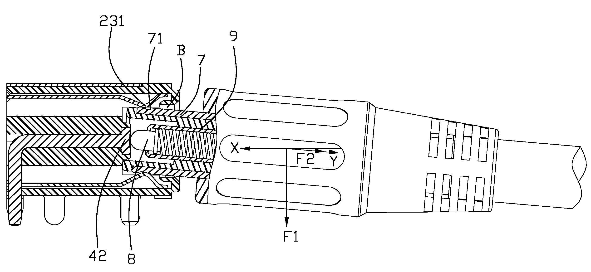
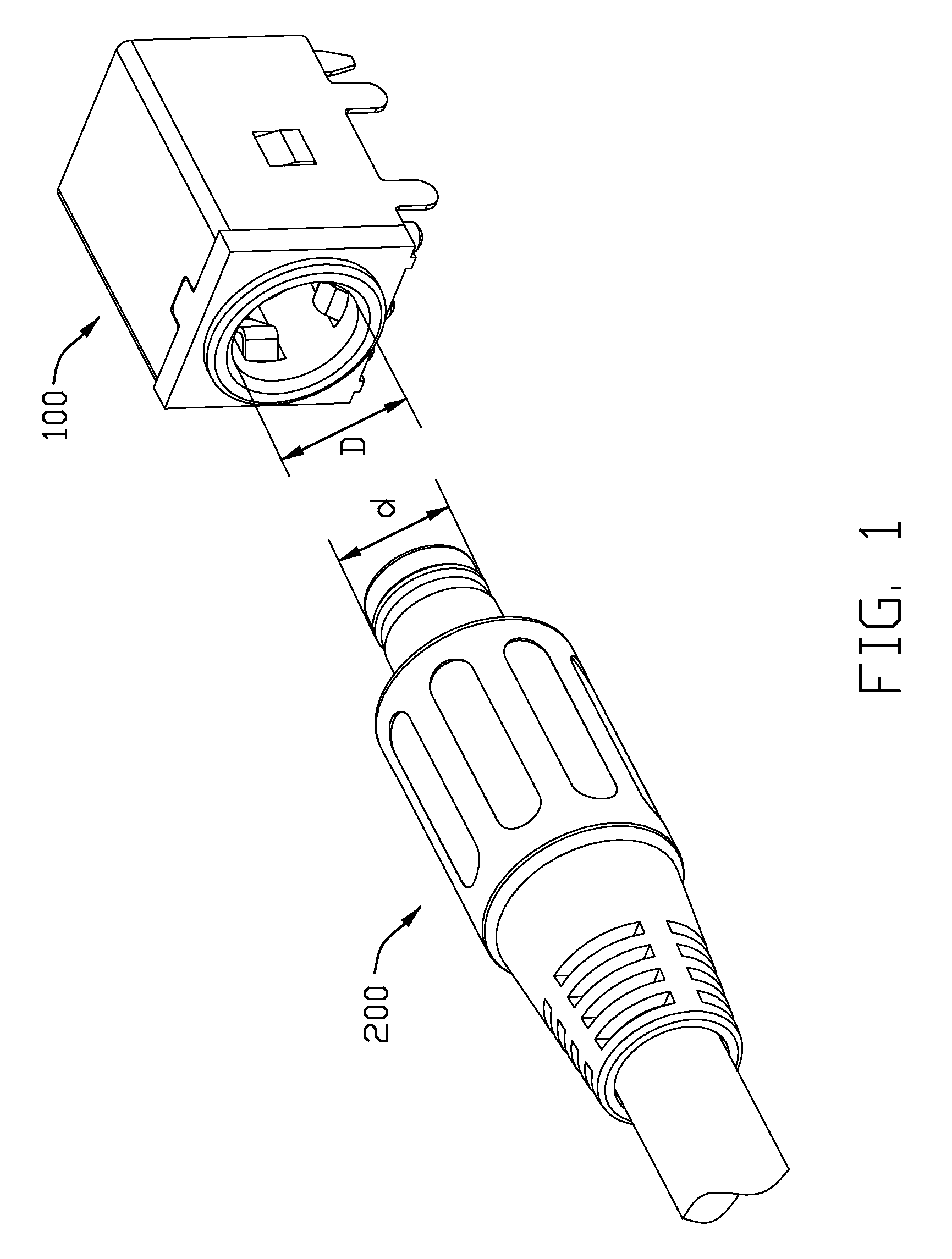
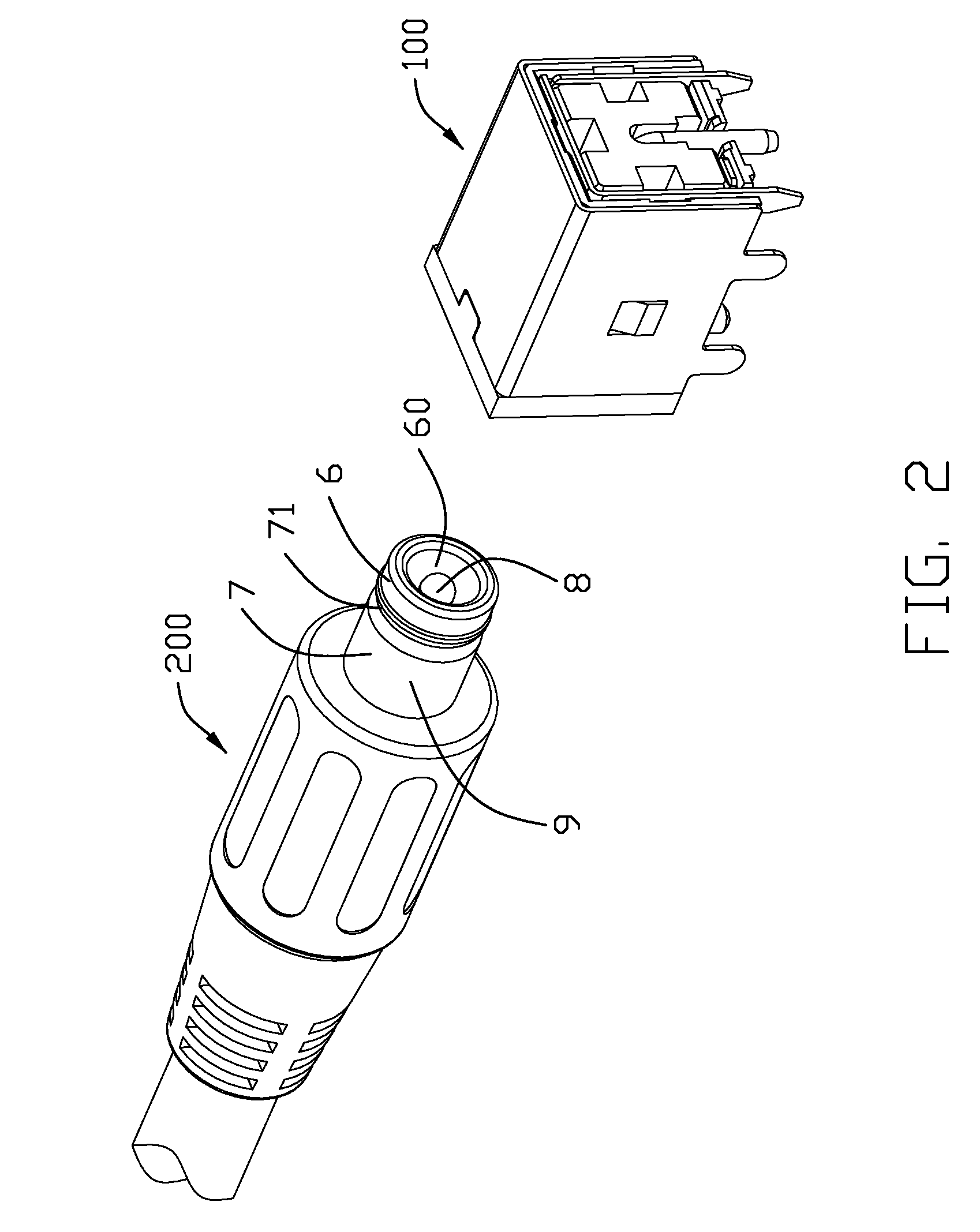
The present invention provides an electrical connector that allows for quick disconnection and dropping of a mating connector in an oblique direction. The connector includes an insulative housing and a plurality of contacts. The housing has a mating face and a supporting face, and a mating cavity recessed from the mating face towards the supporting face. The plurality of contacts includes a central contact and a first contact. The central contact has a contacting portion exposed onto the supporting face and a soldering portion extending out of the housing. The first contact has at least two arc-shaped contacting arms projecting into the mating cavity and disposed besides the contacting portion of the central contact. This design allows for quick and safe disconnection of the mating connectors.

Problems solved by technology

If the force used to pull the plug out of the socket is not perfect align with the insertion direction of the plug, i.e. the pulling force is kind of normal to the plug, then the plug connector will be difficult to be remove therefrom.

Method used


Image

  • Connector assembly featured head-to-head mating interconnection and quick-disconnection therefrom
  • Connector assembly featured head-to-head mating interconnection and quick-disconnection therefrom
  • Connector assembly featured head-to-head mating interconnection and quick-disconnection therefrom

Examples


second embodiment

[0029]FIG. 9 to FIG. 13 shows the invention about a new type connector assembly. The first connector 100′ includes a housing 1′ defining a mating face 10′, a plurality of contacts retained to the housing and a shell 5′ surrounding the housing 1′. A mating cavity 101′ is defined into the mating face 10′ and includes a columnar first receiving cavity 102′ adjacent to the rear face and a second receiving cavity 103′ disposed in front of the first receiving cavity 102′ and extending gradually enlarging toward the mating face 10′ and providing an opening at the mating face 10′ thereof. A supporting face A′ is disposed in the first receiving cavity 102′ and the mating cavity 101′ is disposed between the mating face 10′ and the supporting face A′.

[0030]The plurality of contacts includes a first contact 3′, a second contact 2′ and a central contact 4′. The first contact 3′ defines a circular retaining portion 30′ and four elastic arms 31′ extending forwards from the retaining portion 30′. E...

first embodiment

[0031]The configuration of the insertion portion 9′ of the second connector 200′ is similar to the insertion portion 9 except that the insertion portion 9′ gradually deflates at a front portion thereof to correspond to the second receiving cavity 103′ and defines two metal shells 90′, 91′ surrounding the outside surface thereof. The first shell 90′ surrounds the front portion of the insertion portion 9′ and the second shell 91′ covers the rear portion thereof, and the two shells 90′, 91′ are separated and insulated by an insulative portion 92′. When the insertion portion 9′ is mated with the first connector 100′, the distal end covered by the first shell 90′ is received in the first receiving cavity 102′ with the slot 71′ contacted and clipped by the contacting portions 312′, and the rear portion covered by the second shell 91′ is received in the second receiving cavity 103′ and contacted and clipped by the contacting portion 232′. The contacting portion 42′ exposed onto the support...


PUM


Abstract

An electrical connector (100) includes an insulative housing (10) and a plurality of contacts received to the housing. The housing defines a mating face (10), a supporting face (A) facing to the mating face and a mating cavity (101) recessed from the mating face towards the supporting face and disposed therebetween. The plurality of contacts includes a central contact (4) and a first contact (2), and the central contact defines a contacting portion (42) exposed onto the supporting face and a soldering portion (43) extending out of the housing, the first contact includes at least two arc-shaped contacting arms (23) projecting into the mating cavity and disposed beside the contacting portion of the central contact. A mating connector (200) can be disconnected and dropped from the mating cavity rapidly under an abnormal force oblique and angled to a mating direction.

Description

BACKGROUND OF THE INVENTION[0001]1. Field of the Invention[0002]The present invention relates to a connector assembly, and more particularly to a connector assembly in which male and female connectors are head-to-head interconnected, while can be quickly disengaged with each other by tilting a plug connector.[0003]2. Description of the Related Art[0004]U.S. Pat. No. 6,382,999 issued to Mou et al. on May 7, 2002 discloses an electrical connector assembly including a socket connector and a plug connector mating with the socket connector. The socket connector includes a housing defining a mating cavity opening through a mating face and a plurality of contacts retained to the housing. The plurality of contacts includes a central contact which defines a contacting post projecting into the mating cavity and further adjacent to the mating face. The plug connector includes a contact having a U-shaped contacting portion which defines two separate contacting arms with a receiving room defined...

Claims


Application Information

Patent Timeline
Patent Type & Authority Patents(United States)
IPC IPC(8): H01R24/58
CPCH01R13/631H01R24/50H01R2103/00
Inventor LIN, WEI-CHUNGPENG, BIN
Owner HON HAI PRECISION IND CO LTD
Learn More