
Vacuum assisted prosthetic sleeve and socket utilizing a double membrane liner

a prosthetic and double membrane technology, applied in the field of prosthetic sleeves and sockets, can solve the problems of increased bulk and discomfort, detachment of the socket from the residual limb, and loss of suction within the sealed chamber

Inactive Publication Date: 2011-12-20
SCUSSEL ALFORD SBJ SYST
View PDF24 Cites 27 Cited by
  • Summary
  • Abstract
  • Description
  • Claims
  • Application Information

AI Technical Summary

Benefits of technology

"The present invention is a prosthetic sleeve and socket system with dual skirts that create a sealed chamber between the sleeve and socket when inserted. The system also includes a method for attaching a prosthesis to a residual limb by placing the sleeve around the limb and inserting it into a socket. The method creates a continuous seal between the sleeve and the socket, while removing air from the chamber and creating a partial vacuum to suspend the socket from the residual limb. The dual skirts on the sleeve work with the interior surface of the socket to form the seal and create a continuous connection. The method also includes using a vacuum pump to remove air from the chamber and a wicking material to remove air between the sleeve and the inner skirt. The technical effects of this invention include improved stability and comfort of prosthetic devices and a simplified method for attaching them to residual limbs."

Problems solved by technology

However, these types of suspension systems are bulky and uncomfortable to wear, and when the residual limb was a leg severed above the knee, the socket had to include an ischial flare which only increased bulk and discomfort.
However, since the seal was formed on the outside of the socket it was prone to puncturing which resulted in suction loss within the sealed chamber and detachment of the socket from the residual limb.

Method used


Image

  • Vacuum assisted prosthetic sleeve and socket utilizing a double membrane liner
  • Vacuum assisted prosthetic sleeve and socket utilizing a double membrane liner
  • Vacuum assisted prosthetic sleeve and socket utilizing a double membrane liner

Examples


Embodiment Construction

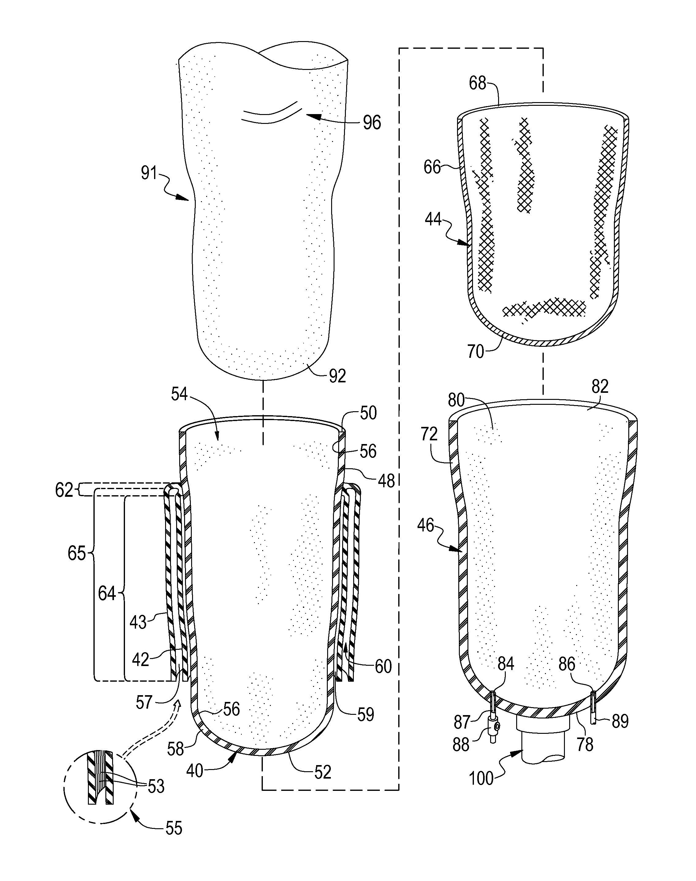
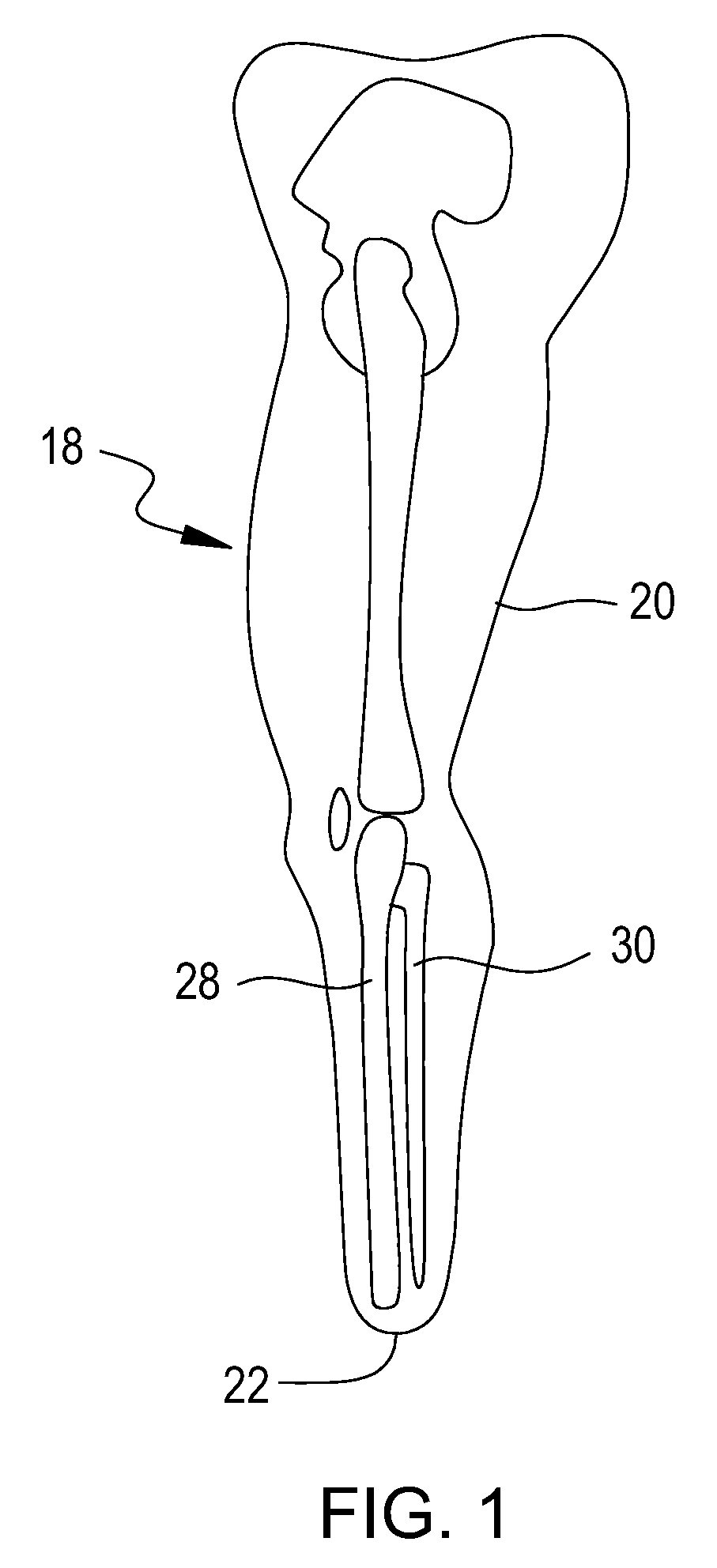
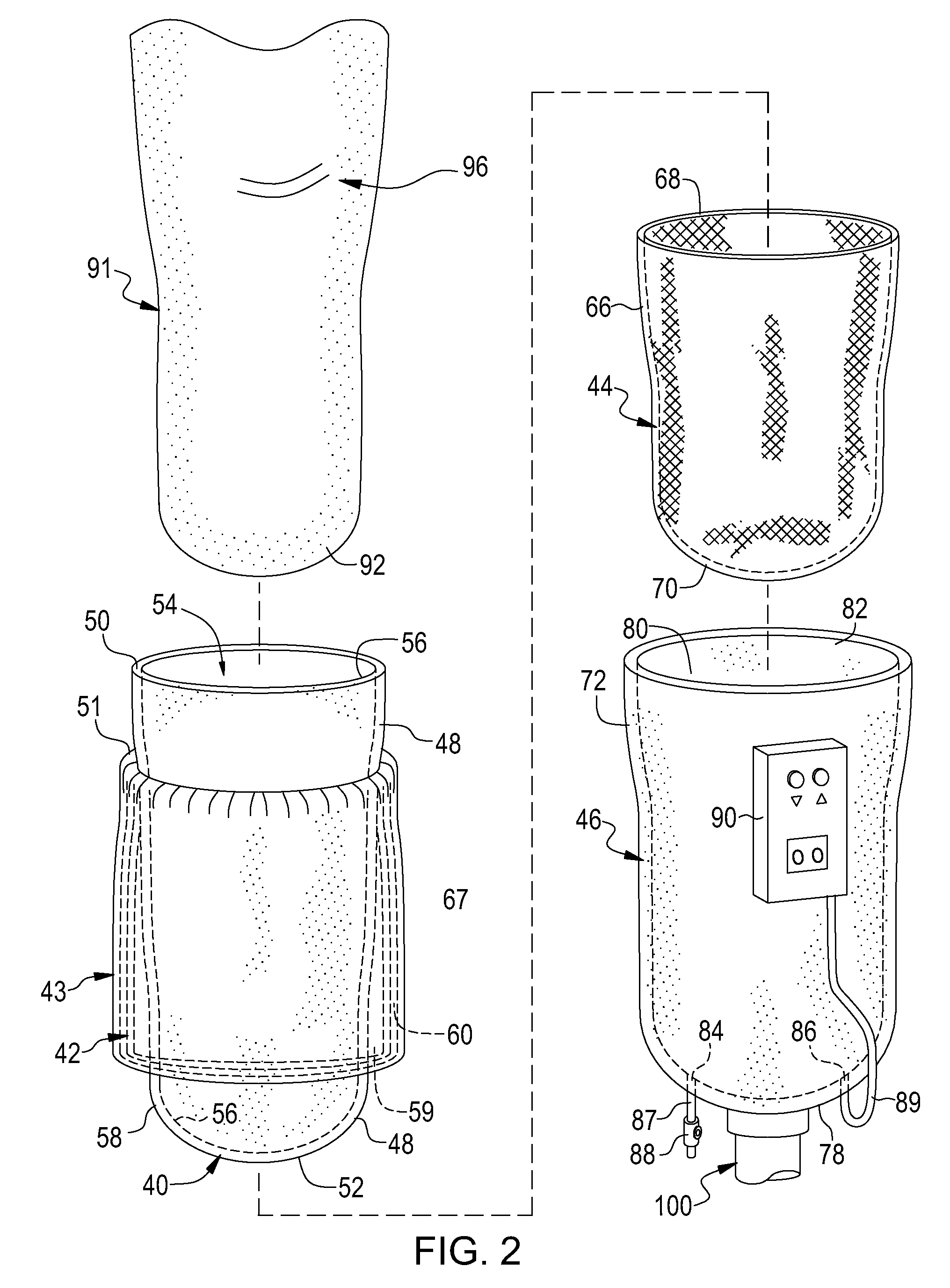
[0015]FIG. 1 illustrates a below the knee residual limb 10 showing relatively low amount of residual flesh around the residual bone and potentially elongated portion. The present invention is illustrated in FIGS. 2-7, where like portions share like numbering. Generally, as illustrated in FIG. 2, the prosthetic sleeve and socket system of present invention includes a pliable, silicone sleeve 40 conformable to the shape of an amputee's residual limb, pliable, dual skirts or flaps 42,43 concentrically arranged about sleeve 40, an air wick 44 and a prosthetic socket 46 conforming to the shape of the amputee's residual limb. “Air wick” is hereby defined as an air permeable material, said material including air permeation characteristics in all directions. For example, a cotton sock would be one form of an air wick. The purpose of the air wick is to avoid the entrapment of air between sleeve 40 and socket 46 and to allow a smooth flow of air over all parts of the sleeve 40 to facilitate t...


PUM


Abstract

A prosthetic sleeve and socket system, the sleeve including dual flaps or skirts concentrically arranged about the sleeve and configured to form a sealed chamber between the sleeve and socket when the sleeve is inserted into the socket. An air permeable material is interposed between one of the skirts and the sleeve to maintain a continuous interconnected air layer therebetween. An expulsion valve is provided to allow air contained within the sealed chamber to be forced out of the chamber ahead of the sleeve when it is inserted into the socket, and a powered vacuum pump maintains the vacuum thereafter, if needed. The system allows for a substantial reduction in size of known sockets and permits, in some instances, the disposal of bulky suspension straps currently in use to force the socket against a residual limb.

Description

[0001]This application claims the benefit of filing priority under 35 U.S.C. §119 and 37 C.F.R. §1.78 from U.S. Provisional Application Ser. No. 60 / 904,833 filed Feb. 5, 2007, for SCUSSEL / SBJ SUCTION LINER-SOCKET, and the non-provisional patent application Ser. No. 11 / 762,306 filed Jun. 13, 2007, for VACUUM ASSISTED PROSTHETIC SLEEVE AND SOCKET. All information disclosed in those prior applications is incorporated herein by reference.FIELD OF THE INVENTION[0002]This invention relates to a prosthetic sleeve and socket combination, and more particularly, to a prosthetic sleeve having dual flaps or skirts concentrically arranged about the sleeve and configured to form a sealed chamber between the sleeve and socket when the sleeve is inserted into the socket.BACKGROUND OF THE INVENTION[0003]An amputee is a person who has lost part of an extremity or limb such as a leg or arm. That which remains is commonly referred to as a residual limb. Residual limbs come in various sizes and shapes w...

Claims


Application Information

Patent Timeline
Patent Type & Authority Patents(United States)
IPC IPC(8): A61F2/78A61F2/80A61F2/60
CPCA61F2/7812A61F2/80A61F2002/742A61F2002/7806A61F2002/807A61F2002/7868A61F2002/802A61F2002/805A61F2002/7818A61F2/742
Inventor SCUSSEL, RICK C.ALFORD, DAVID WILEY
Owner SCUSSEL ALFORD SBJ SYST
Learn More