Mitigating recoil in a ballistic robot

a technology of ballistic robots and recoils, which is applied in the field of ballistic or projectile firing systems, can solve the problems of injuring operators, affecting the safety of operators, etc., and achieves the effects of simple recoil mitigation, easy attachment and detachability, and minimal binding or lateral pitching

Active Publication Date: 2011-12-27
FLIR DETECTION
View PDF27 Cites 28 Cited by
  • Summary
  • Abstract
  • Description
  • Claims
  • Application Information

AI Technical Summary

Benefits of technology

[0007]Accordingly, there is a need for a recoil mitigation device for use with disrupters and various other ordnances mounted on robotic platforms. There is a need for a recoil mitiga

Problems solved by technology

Such systems are often complex, expensive, and applicable to a single firing system into which it is integrated.
Many such systems position the mitigation device entirely to one side of the firing system and may thus cause binding of the mitigation device or firing system or pitching of the firing device due to the presence of resistance to recoil only from one side.
Recoil affects the targeting accuracy of the firing system

Method used


Image

  • Mitigating recoil in a ballistic robot
  • Mitigating recoil in a ballistic robot
  • Mitigating recoil in a ballistic robot

Examples


Embodiment Construction

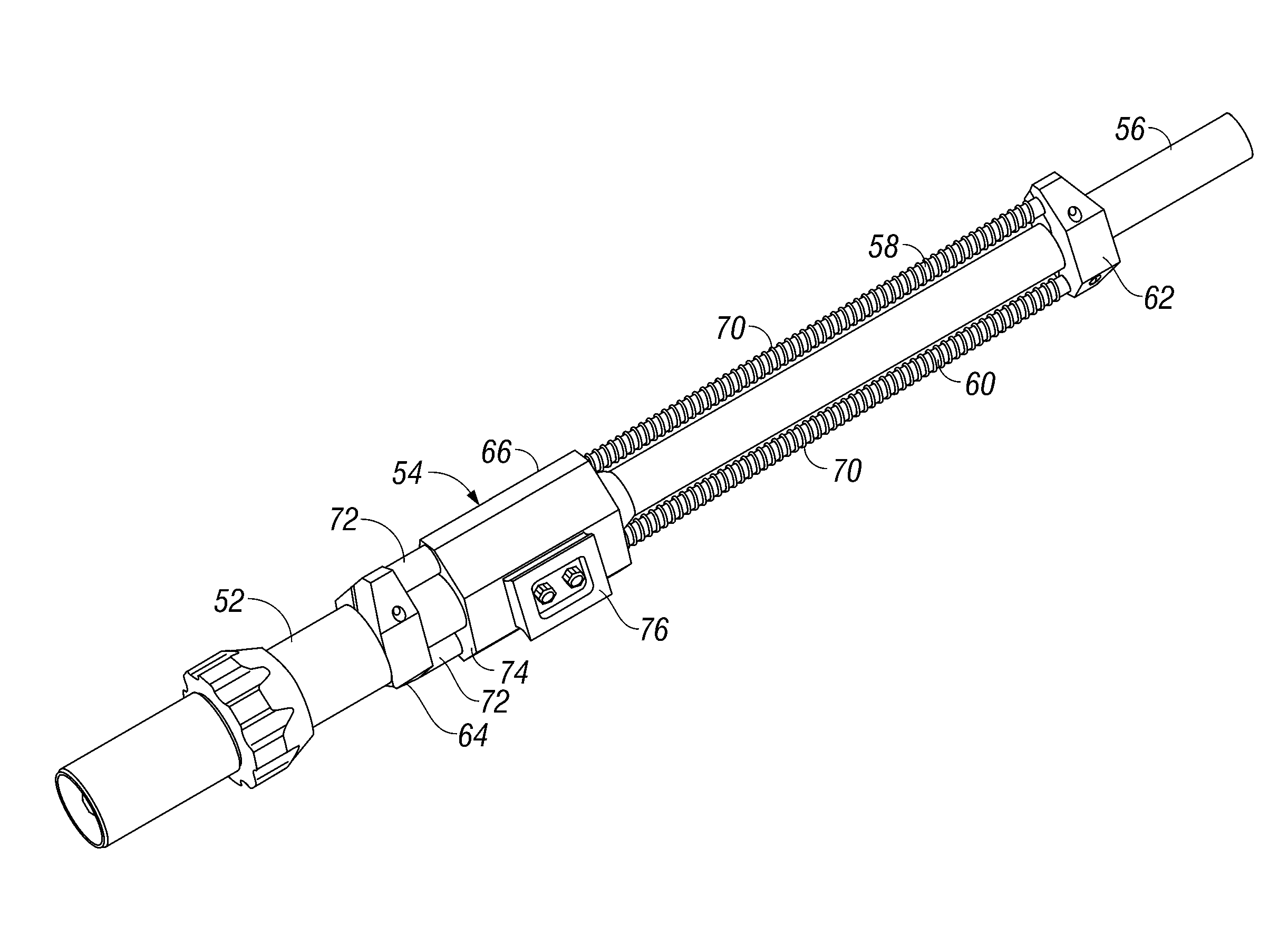
[0042]A recoil mitigation device (“recoilless mount”) provides dampening of recoil generated during discharge of a projectile from a projectile firing device such as a disrupter. In various embodiments, recoil damping is provided by a pair of gas shocks or gas springs interposed between the disrupter and the disrupter support platform. In other embodiments, recoil damping is provided by a pair of rails carrying coil springs and a rail carriage, the rails being connected to the disrupter barrel and the rail carriage being connected to the disrupter support platform.

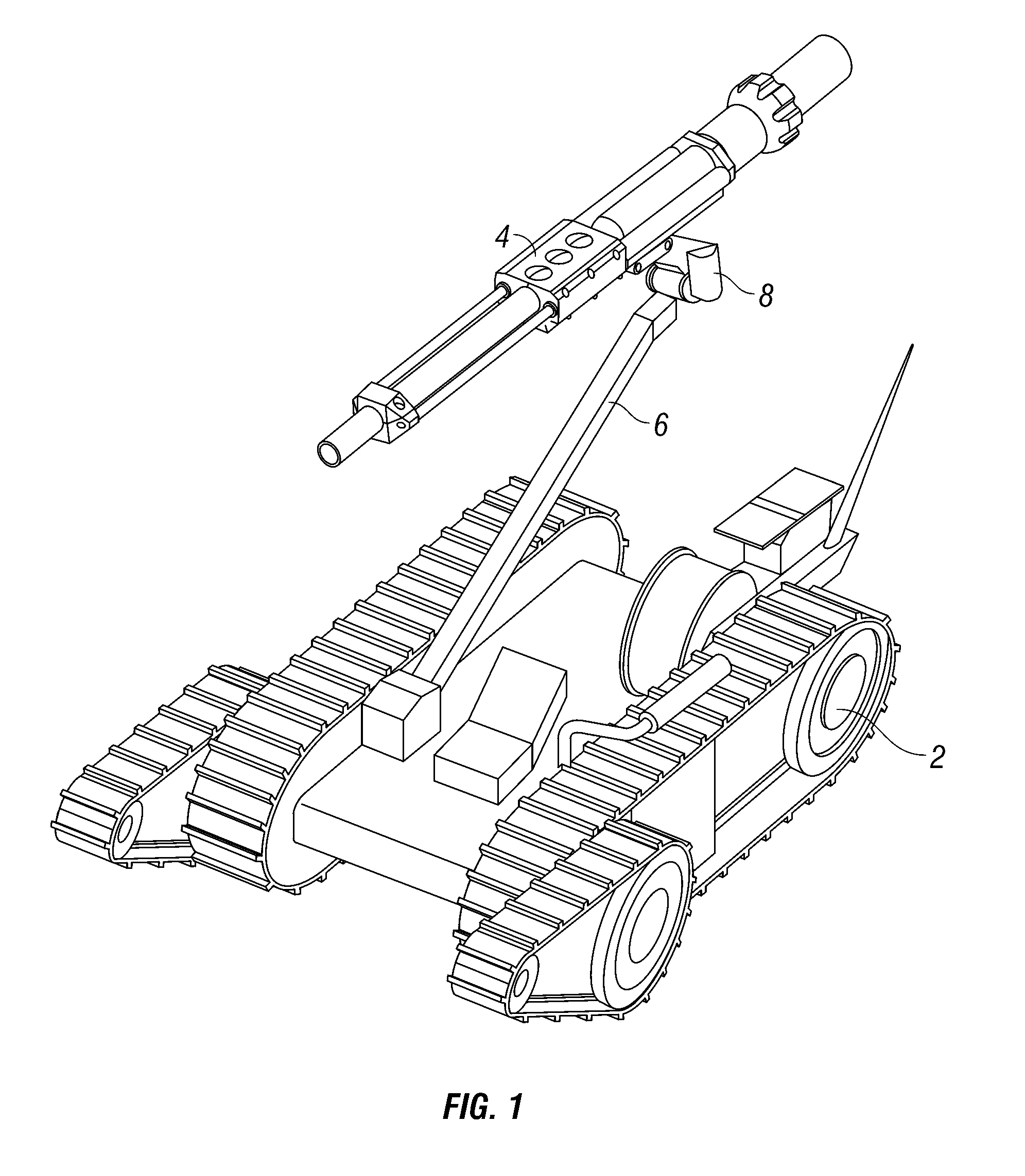
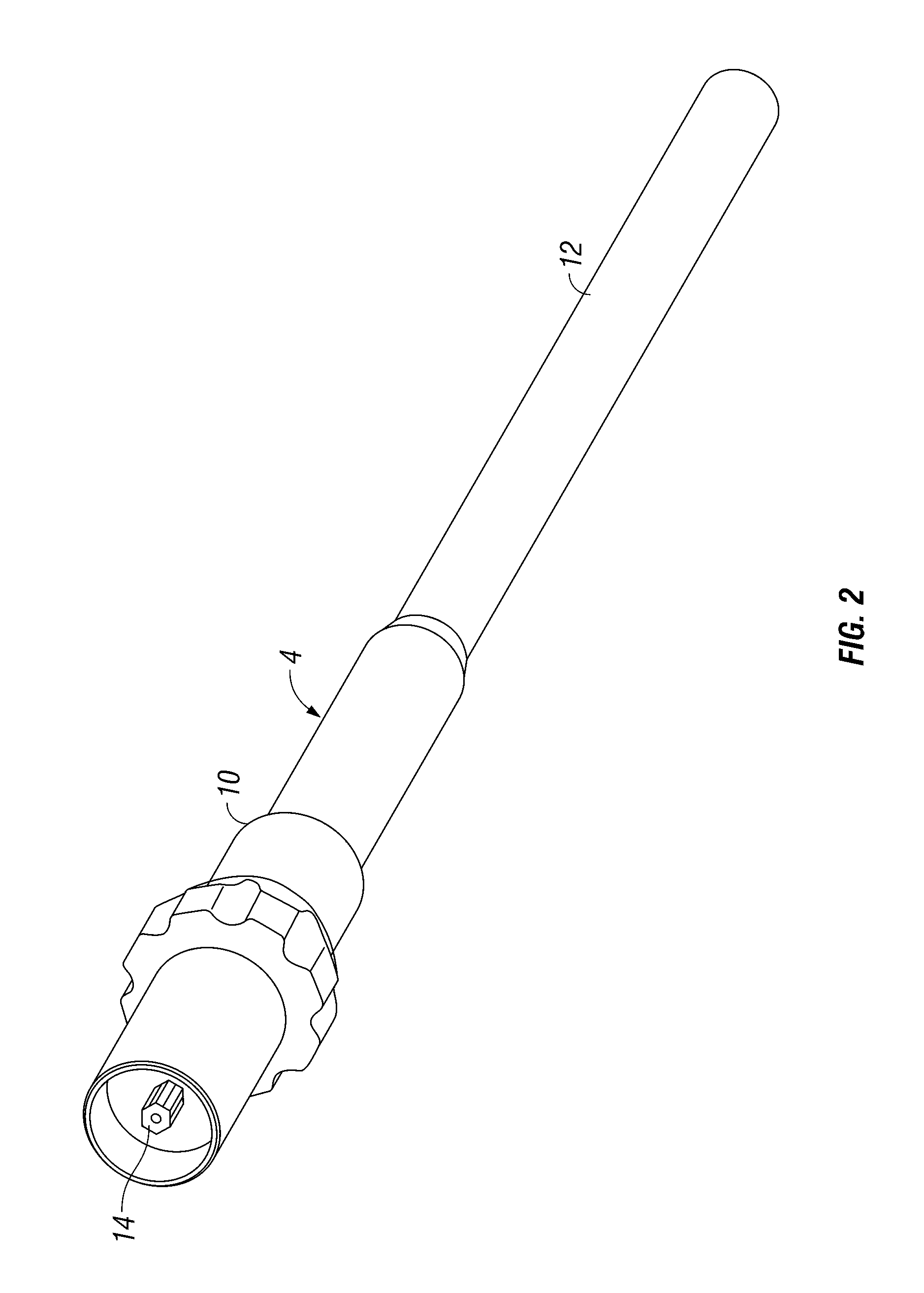
[0043]Preferred embodiments may be used to mitigate recoil experienced by any support platform carrying a projectile firing device. That being said, the embodiments described herein are shown in the context of a disrupter mounted on a robotic arm. Thus, “disrupter” as used herein, generally includes any launcher, projectile firing device or ordnance. Similarly, “robot” and “robot arm” generally includes any non-human ordna...


PUM


Abstract

Recoil mitigating devices and methods for use with projectile firing systems such as a disrupter mounted to a robotic arm. A pair of parallel spring provides dampening of axial recoil movement of the disrupter relative to the robotic arm. Forward ends of the springs are attachable to the barrel of the disrupter while rearward portions of the springs are attachable to the robotic arm by a robot mount block. The robot mount block at least partially encloses the barrel of the disrupter in connecting the parallel springs and permits axial movement of the disrupter along or through the mount during firing.

Description

CROSS-REFERENCE TO RELATED APPLICATIONS[0001]This application is a divisional of U.S. application Ser. No. 12 / 061,476, filed Apr. 2, 2008 now U.S. Pat. No. 7,878,105, which claims priority under 35 U.S.C. §119(e) to U.S. provisional patent application Ser. No. 60 / 909,630, filed on Apr. 2, 2007, the entire contents of which are hereby incorporated by reference.TECHNICAL FIELD[0002]This invention relates to ballistic or projectile firing systems, and more particularly to devices and methods for mitigating recoil during operation of such systems.BACKGROUND[0003]Ballistic weapons or other projectile firing systems, typically generate recoil forces proportionate to the discharge forces or the mass and acceleration of the projectile. The resulting recoil impulse or “kick” corresponds to the recoil force integrated over time. A recoil mitigation device serves to attenuate or dampen the force-time profile during discharge, for example, to create a longer, lower amplitude recoil impulse.[000...

Claims


Application Information

Patent Timeline
IPC IPC(8): F41A25/02F41A25/10
CPCF41A25/04F41H7/005F41H11/16
Inventor MORE, GRINNELL
Owner FLIR DETECTION
Why Eureka
Try Eureka