Golf ball mold, golf ball and method of manufacturing a golf ball

a golf ball and mold technology, applied in the field of golf ball molds, golf balls and methods of manufacturing golf balls, can solve the problems of variability in flight performance, lack of uniformity in aerodynamic symmetry of balls, and difficulty in achieving uniform arrangement of dimples on the spherical surface of balls, etc., and achieves stable molding and easy to increase the surface coverage of dimples.

Active Publication Date: 2011-12-27
BRIDGESTONE SPORTS
View PDF30 Cites 11 Cited by
  • Summary
  • Abstract
  • Description
  • Claims
  • Application Information

AI Technical Summary

Benefits of technology

[0009]It is therefore an object of the present invention to provide a golf ball mold which makes it easy to increase the dimple surface coverage, enables an injection port having an opening with a specific surface area to be provided even when the dimples are densely formed, and enables stable molding to be carried out without giving rise to the above-described production problems. Further objects of the invention are to provide a golf ball molded using such a mold and a method of manufacturing golf balls using such a mold.
[0022]In the golf ball mold of the present invention, by forming a non-circular resin injection port between a plurality of mutually adjoining dimple-forming protrusions which include dimple-forming protrusions that lie across a parting line of the mold, the shape of the injection port is not limited to the ordinary circular or oval shapes of conventional injection ports, thus making it possible to ensure that the injection port has at least a given cross-sectional surface area even when the interval between the adjoining dimples has been made smaller than in the prior art. Therefore, even when the dimples are tightly arranged in the vicinity of the parting line so as to increase the surface coverage of the dimples, a resin injection port having an opening of a given surface area can be provided without being affected by the dimple configuration.
[0023]Also, by using the mold of the invention, even when manufacturing golf balls with a high dimple surface coverage on which the dimples are tightly arranged particularly up to the vicinity of the resin injection port, imbalances in the resin injection pressure and flow rate during injection molding are suppressed, enabling golf balls to be manufactured without giving rise to production problems such as molding defects, scorching, core deformation and core eccentricity.
[0024]In addition, because golf balls molded using the inventive mold have a high dimple surface coverage and symmetry, the aerodynamic properties can be improved, enabling an excellent flight performance to be achieved and making it possible to minimize the variability of flight.

Problems solved by technology

However, in a golf ball having at the equator a wide great circle across which there lie no dimples, it is difficult to achieve a uniform arrangement of dimples on the spherical surface of the ball.
This leads to a lack of uniformity in the aerodynamic symmetry of the ball, giving rise to a variability in the flight performance due to differences on where the ball is hit.
Yet, imbalances in the resin injection pressure or flow rate often arise.
Hence, when a cover is formed over a core or a sphere composed of a core encased by another layer such as an intermediate layer, the core may end up deformed or the position of the core within the mold may end up off-center, leading to various problems, such as molding defects, scorching or eccentricity.
Golf balls with these problems have an inferior quality, such as durability, symmetry and appearance.
However, a fundamental solution to the conflicting problems of mold design and dimple design has yet to be achieved.

Method used


Image

  • Golf ball mold, golf ball and method of manufacturing a golf ball
  • Golf ball mold, golf ball and method of manufacturing a golf ball
  • Golf ball mold, golf ball and method of manufacturing a golf ball

Examples


Embodiment Construction

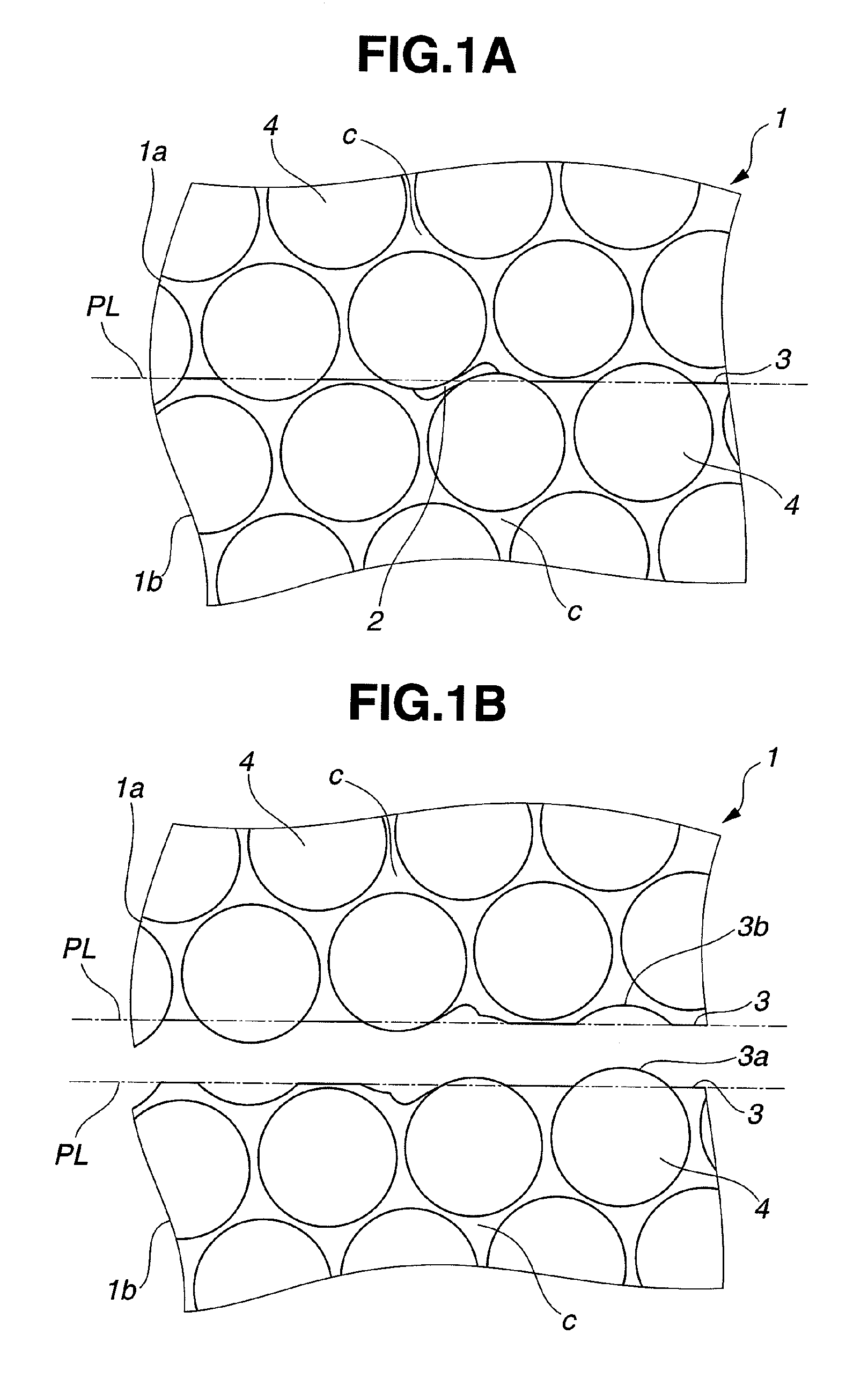
[0034]The golf ball mold of the invention is described more fully below in conjunction with the appended diagrams.

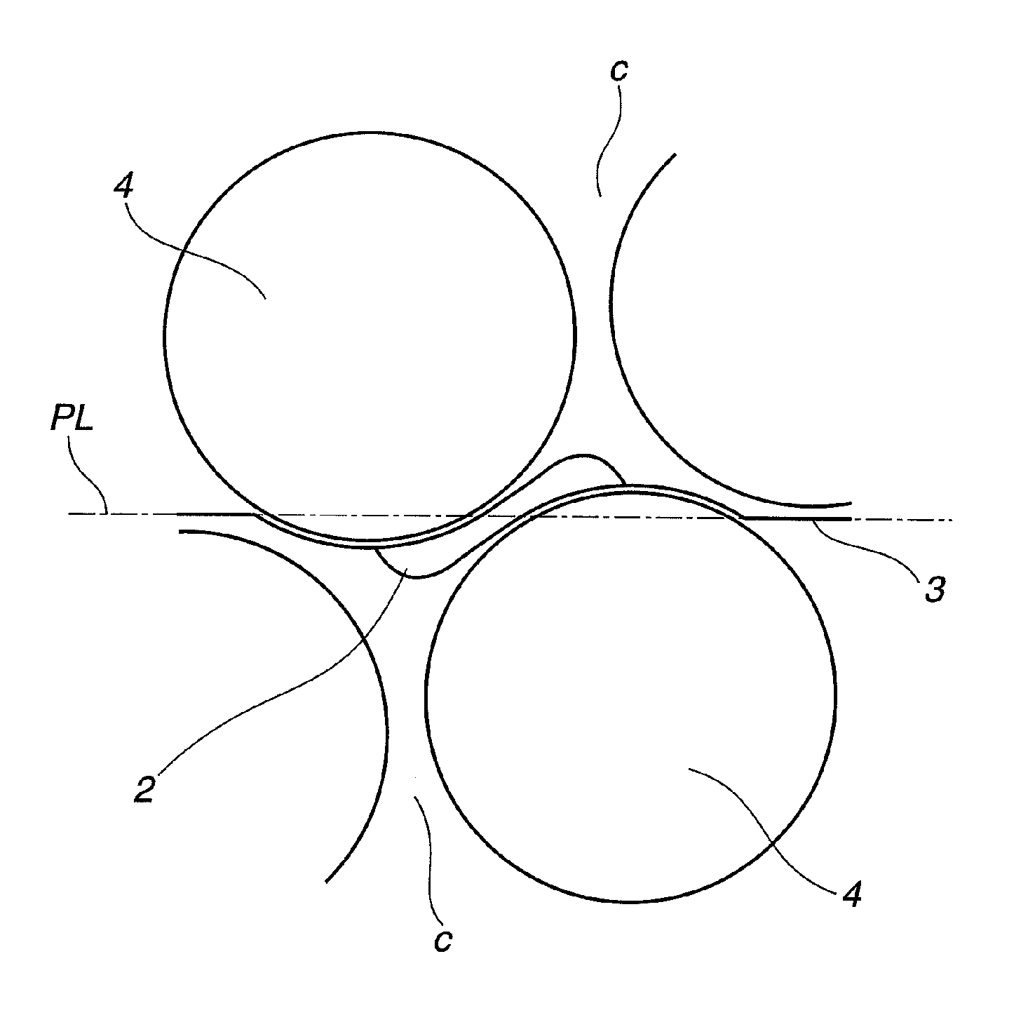
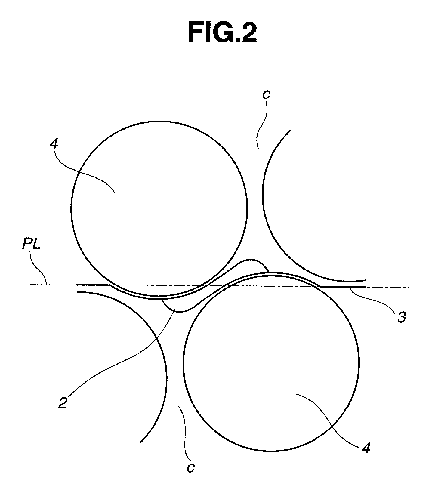
[0035]The “parting line” and “parting plane” of the mold, as used in the description below, are defined as follows.

[0036]The “parting line” is a line that serves as a reference when the mold splits into a plurality of parts. For example, in the case of a mold that splits into two parts, the parting line refers to a line that serves as a reference for the mating of the upper mold half with the lower mold half, and is rectilinear. The “parting plane” of the mold refers to the area of contact when the respective mold parts that have been separated based on the above parting line are joined together. In the present invention, because a plurality of dimple-forming protrusions that lie across the parting line are provided on the parting plane, the parting plane has convex features due to the dimple-forming protrusions and also has concave features which correspond to the conve...


PUM

PropertyMeasurementUnit
surface areaaaaaaaaaaa
aspect ratioaaaaaaaaaa
diameteraaaaaaaaaa

Abstract

A golf ball mold that is composed of a plurality of mold parts which removably mate to form a cavity having an inner wall with a plurality of dimple-forming protrusions thereon, wherein a non-circular resin injection port is formed between a plurality of mutually adjoining dimple-forming protrusions which include dimple-forming protrusions that lie across a parting line of the mold. Also provided is a golf ball molded using such a mold, and a golf ball manufacturing method which uses such a mold. By using the mold of the invention, even when manufacturing golf balls with a high dimple surface coverage on which the dimples are tightly arranged particularly up to the vicinity of the resin injection port, imbalances in the resin injection pressure and flow rate during injection molding are suppressed, enabling golf balls to be manufactured without production problems such as molding defects, scorching, core deformation and core eccentricity.

Description

BACKGROUND OF THE INVENTION[0001]The present invention relates to a golf ball mold suitable for molding solid golf balls composed of a core encased by one or more cover layer, and thread-wound golf balls. The invention relates also to golf balls molded using such a mold, and to a method of manufacturing golf balls using such a mold.[0002]Molds for molding golf balls are generally composed of a plurality of parts which removably mate to each other; a golf ball is manufactured by feeding a golf ball molding material to a cavity that forms at the interior of the mold when these mold parts are mated. From the standpoint of ease of mold fabrication and ball moldability, etc., the parting plane of each mold part is often rectilinear in shape without concavities and convexities. Parting planes having such a rectilinear shape are often coincident with the equator of the golf ball. Thus, in golf balls molded with such a mold, dimples are not formed on the equator which corresponds to the par...

Claims


Application Information

Patent Timeline
Patent Type & Authority Patents(United States)
IPC IPC(8): B29C70/70B29C45/14
CPCA63B45/00B29C45/2708B29C45/372A63B37/0005A63B37/0004B29L2031/54A63B37/0033A63B37/0006A63B37/0018A63B37/0019A63B37/002A63B37/0021
Inventor NAKAGAWA, TAKUMASATO, KATSUNORI
Owner BRIDGESTONE SPORTS
Why Eureka
Try Eureka