Generator/motor mounted as an auxiliary power unit of an engine

a technology of generator/motor and engine, which is applied in the direction of engine-driven generators, electric devices, and magnetic circuit shapes/forms/construction, etc., can solve the problems of reducing the output of the motor, deteriorating the rotation precision of the motor rotor, and extremely difficult to manage the air gap between the stator core and the magnetic pole, so as to enhance the rotation efficiency of the generator. , the effect of enhancing the rotation efficiency of the engin

Inactive Publication Date: 2011-12-27
KOMATSU LTD
View PDF14 Cites 15 Cited by
  • Summary
  • Abstract
  • Description
  • Claims
  • Application Information

AI Technical Summary

Benefits of technology

[0015]According to the generator / motor of the hybrid engine according to the present invention, the motor rotor is rotatably supported by the support portion of the motor housing which is a rigid body through a bearing. As a result, surface vibration or core vibration is not generated in the rotation of the motor rotor. The cylindrical shaft portion is disposed between the motor rotor and the crankshaft portion of the engine so that the vibration of the crankshaft portion is not transmitted directly to the motor rotor. Especially, the cylindrical shaft portion and the crankshaft portion are spline coupled to each other. With such spline coupling, the machining precision can easily be adjusted depending upon design of the meshing tooth. In this invention, a fine clearance is provided in the spline coupling so that a free degree is given to the fitted portions. With this clearance, even if the crankshaft receives vibration of the engine and the core vibrates, the core vibration is attenuated through the cylindrical shaft portion, the rotation precision of the motor rotor is maintained for a long time, and the air gap between the stator core is maintained constant for a long term. As a result, the motor efficiency and the power generating efficiency of the generator / motor of the invention are not deteriorated.
[0016]In the invention, when a plurality of spline couplings is established through the cylindrical shaft portion, the respective spline coupled portions are independently formed with spline tooth. Thus, it is possible to prevent each spline coupled portion from receiving direct influence from each other, and power can be transmitted between the cylindrical shaft portion and the crankshaft portion and between the cylindrical shaft portion and the motor rotor with independent motion.
[0017]The crankshaft portion of the invention is a crankshaft itself of the engine but includes a flywheel which is integrally fixed to the crankshaft in some cases. The flywheel in this case enhances the rotation efficiency of the engine and rotation efficiency of the generator and thus, the flywheel functions as both the engine and the generator / motor. There are a case where the cylindrical shaft portion is independent from the motor rotor, a case where the cylindrical shaft portion exists alone, and a case where the cylindrical shaft portion includes first and second shaft bodies. The cylindrical shaft portion may be integral with the motor rotor. Depending upon the various combinations of the structures, there are a case where the cylindrical shaft portion and the crankshaft are directly spline coupled to each other, and a case where the cylindrical shaft portion and the flywheel are spline coupled to each other.
[0018]At any rate, in this invention, the motor rotor is rotatably supported by a portion of the motor housing which is a rigid body through a bearing, and they are spline coupled to each other at least between the motor rotor and the crankshaft portion through the cylindrical shaft portion. Therefore, vibration generated in the crankshaft portion with respect to the motor rotor, surface or core vibration of the flywheel can be suppressed to the utmost, and stable rotation precision can be obtained in the motor rotor.

Problems solved by technology

Since the flywheel is directly connected to a crankshaft, if a motor rotor is fixed to the flywheel, a surface and a core of the flywheel vibrate, the rotation precision of the motor rotor is deteriorated, and it becomes extremely difficult to manage an air gap between a stator core and a magnetic pole.
However, if the air gap is increased in this manner, the output of the motor is reduced and the power generating efficiency is also deteriorated.

Method used


Image

  • Generator/motor mounted as an auxiliary power unit of an engine
  • Generator/motor mounted as an auxiliary power unit of an engine
  • Generator/motor mounted as an auxiliary power unit of an engine

Examples


first embodiment

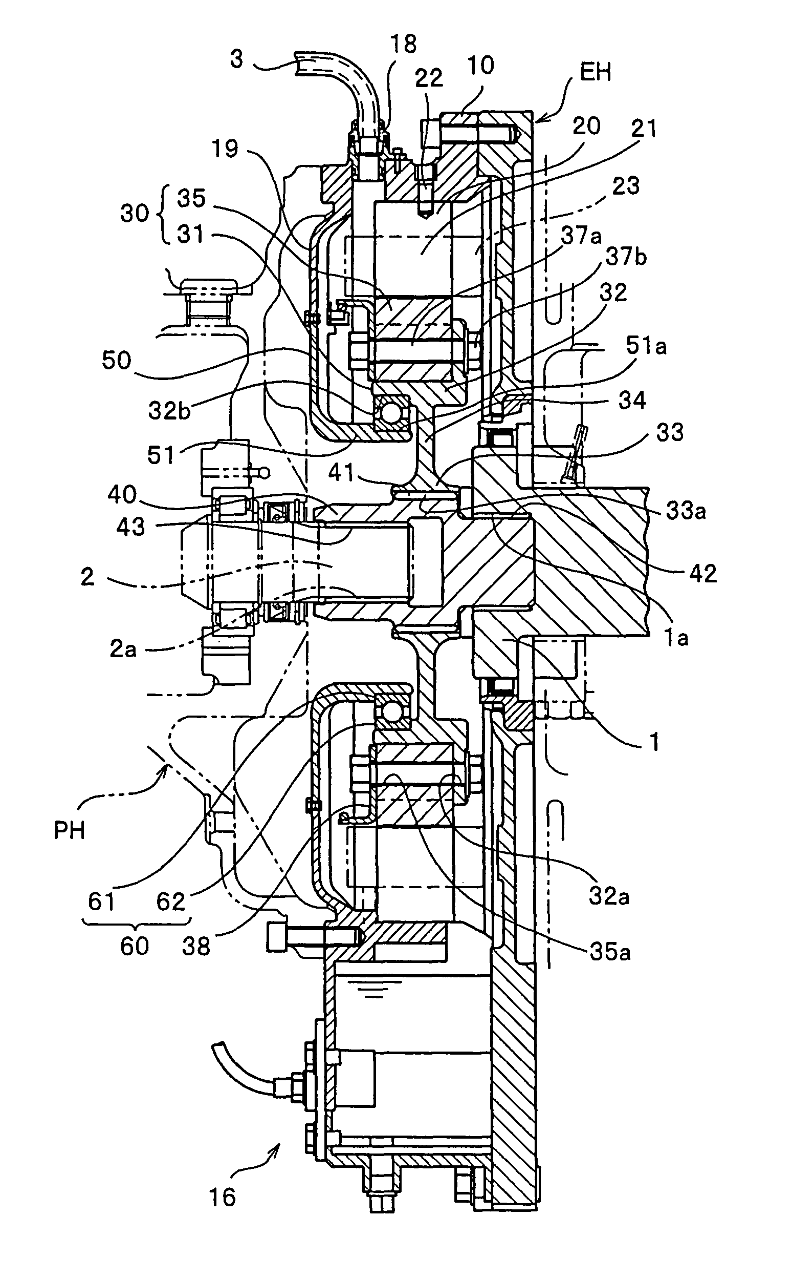
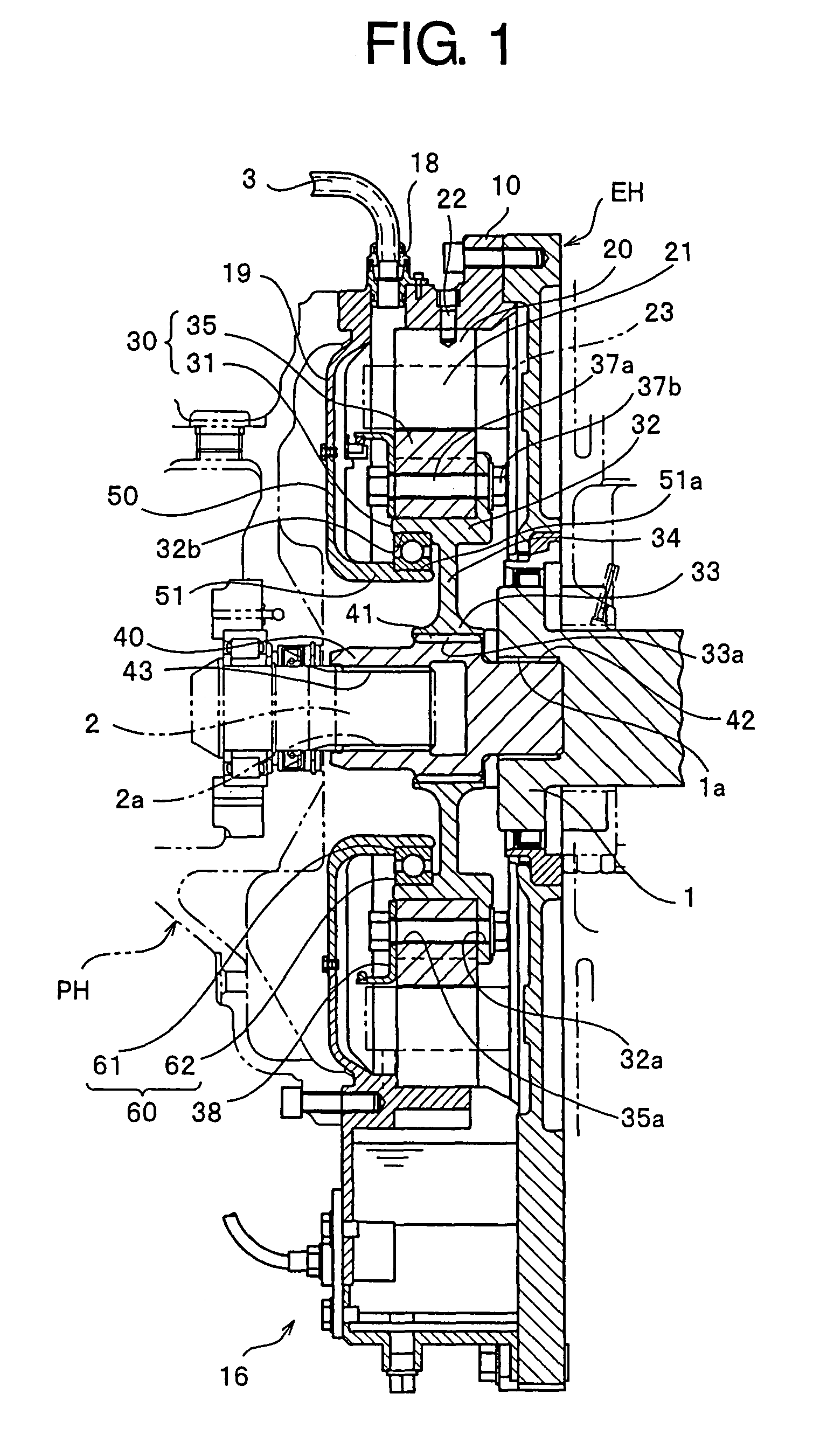
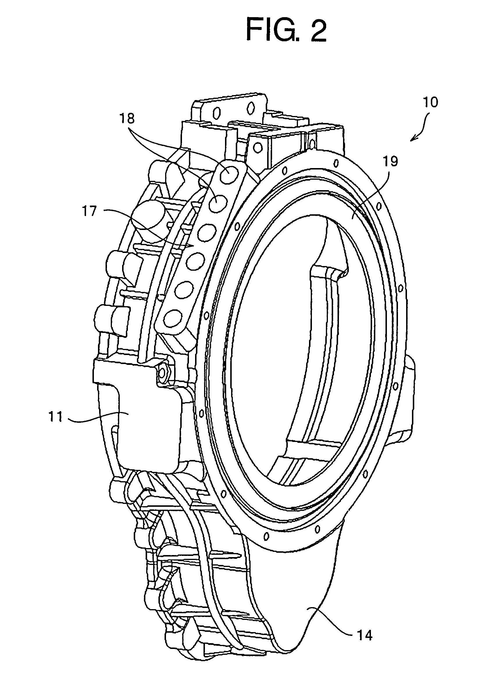
[0092]Representative embodiments of the present invention will be explained concretely based on the drawings. FIG. 1 is a vertical sectional view taken along an axis of a generator / motor according to the invention. FIGS. 2 to 9 are perspective views of main constituent members of the generator / motor. The generator / motor of the embodiment is mounted in a hybrid engine applied to a construction equipment such as a hydraulic shovel but can widely be applied to other automobile fields, general industrial machine fields or large engine such as shipping.

[0093]As can be understood from these drawings, main constituent members of the generator / motor in the illustrated embodiment are a motor housing 10, a ring-shaped stator core 20 fixed to an inner wall surface of the motor housing 10, a motor rotor 30 opposed to an inner peripheral surface of the stator core 20, a cylindrical shaft portion 40 as one of constituent members of the motor rotor 30 which is inserted through a center hole of the...

fourth embodiment

[0116]FIGS. 13 and 14 show a rotor flange applied to a generator / motor according to the present invention, FIG. 13 is a perspective view of the rotor flange as viewed from the engine and FIG. 14 is a perspective view thereof as viewed from the pump.

[0117]In the first to third embodiments, the rotor flange 31 and the cylindrical shaft portion 40 are separately manufactured, and they are spline coupled to each other by means of the internal tooth splines and the external tooth splines. In the fourth embodiment, the rotor flange 31 and the cylindrical shaft portion 40 are integrally manufactured by molding. In the generator / motor of the hybrid engine of the invention, the motor rotor 30 is rotatably supported by the yoke support 32 of the motor housing 10 which is a rigid body through the bearing 60. As a result, surface vibration or core vibration is not generated in the rotation of the motor rotor 30. Corresponding structures of the first to third embodiments can be employed as the o...


PUM


Abstract

A generator / motor includes a ring-shaped stator core (20) fixed to a motor housing (10), and a motor rotor (30). The motor rotor (30) includes a ring-shaped rotor yoke (35) which rotates in cooperation with the crankshaft (1) and which is opposed to an inner peripheral surface of the stator core (20) with a predetermined gap therebetween. The motor rotor (30) also includes a rotor flange (31) which fixes and supports the rotor yoke (35) at its outer peripheral surface. The rotor flange (31) is rotatably supported by a support member (51a) of the motor housing (10) through a bearing (60). A cylindrical shaft portion (40) is interposed between the crankshaft (1) and the motor rotor (30), and the crankshaft (1) is spline coupled to the cylindrical shaft portion (40).

Description

TECHNICAL FIELD[0001]The present invention relates to a generator / motor which is mounted in an automobile or construction equipment and which is suitable as an auxiliary power unit of a hybrid engine.BACKGROUND ART[0002]In some commercially available vehicles including passenger cars, buses and trucks, a generator / motor has already been mounted in a flywheel of a hybrid engine thereof. As a hybrid power unit, an engine may be provided with a PTO and a special power generator may be mounted, but if a flywheel and a generator / motor are integrally formed, there are merits that two functions are commonly used, the number of parts is reduced, and a vehicle space for mounting the power generator may be small. Thus, in this specification, a flywheel which is integrally fixed to a crankshaft is handled as one of constituent members of the generator / motor.[0003]Since the flywheel is directly connected to a crankshaft, if a motor rotor is fixed to the flywheel, a surface and a core of the fly...

Claims


Application Information

Patent Timeline
Patent Type & Authority Patents(United States)
IPC IPC(8): H02K49/00H02K47/00H02K1/00H02K7/10B60L50/16
CPCB60K6/26B60K6/485H02K1/28H02K5/24H02K7/003H02K7/006H02K7/085H02K7/1815B60L3/0061B60L11/14B60K6/40Y02T10/641H02K1/246H02K7/16H02K9/19Y02T10/6226B60L2210/40B60L2240/36B60L2270/145Y02T10/7077Y02T10/7241Y02T10/70B60L50/16Y02T10/62Y02T10/64Y02T10/7072Y02T10/72H02K1/24
Inventor CHIBA, TEIICHIROU
Owner KOMATSU LTD
Why Eureka
Try Eureka